Plasma gasification equipment for changing garbage raw material to be syngas of high heat value

A technology of plasma and gasification equipment, applied in the field of garbage treatment equipment, can solve the problems of low calorific value, low calorific value of synthesis gas, small economic output/input ratio, etc., and achieves simple equipment structure, high energy conversion rate, The effect of relieving energy stress

Inactive Publication Date: 2008-11-19
衢州市广源生活垃圾液化技术研究所
View PDF0 Cites 22 Cited by
  • Summary
  • Abstract
  • Description
  • Claims
  • Application Information

AI Technical Summary

Problems solved by technology

At present, China's treatment of municipal solid waste mainly includes sanitary landfill technology, composting (biochemical) technology and incineration technology. Most areas use sanitary landfill to treat municipal solid waste, which not only takes up a lot of land, wastes resources, but also easily pollutes Land and groundwater; composting only utilizes about 40% of organic matter, and it is necessary to build supporting incineration process equipment and sanitary landfills. Heavy metals in composting products may pollute the soil and enter the food chain crops. There are hidden dangers of secondary pollution; using the incineration power generation method to deal with urban domestic waste can reduce the amount and recycle domestic waste, but waste incineration power generation has the following disadvantages: 1. The main goal is to treat waste, and the energy utilization rate is low. Only about 20%; 2. The emissions of flue gas and carbon dioxide are large, and the pollutants in the flue gas include du

Method used


Image

  • Plasma gasification equipment for changing garbage raw material to be syngas of high heat value
  • Plasma gasification equipment for changing garbage raw material to be syngas of high heat value
  • Plasma gasification equipment for changing garbage raw material to be syngas of high heat value

Examples


Embodiment Construction

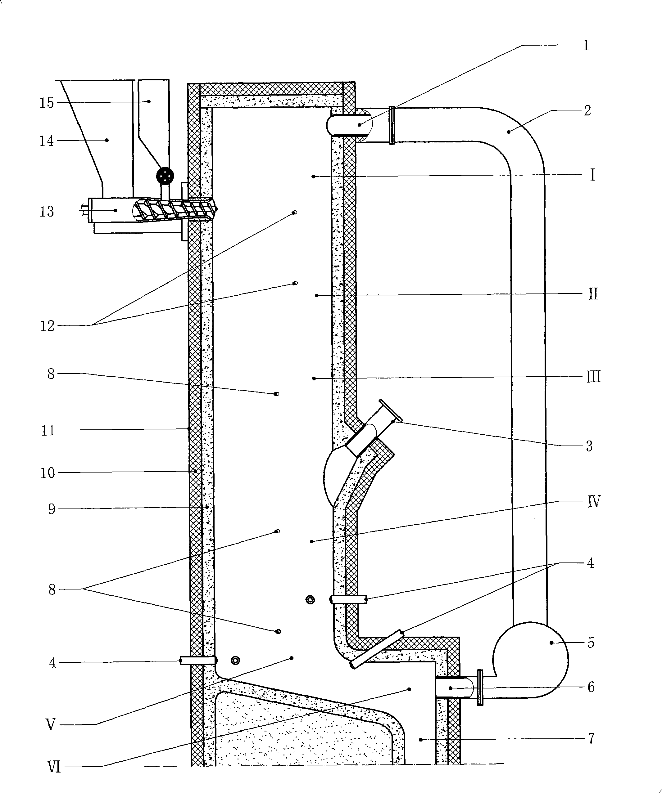
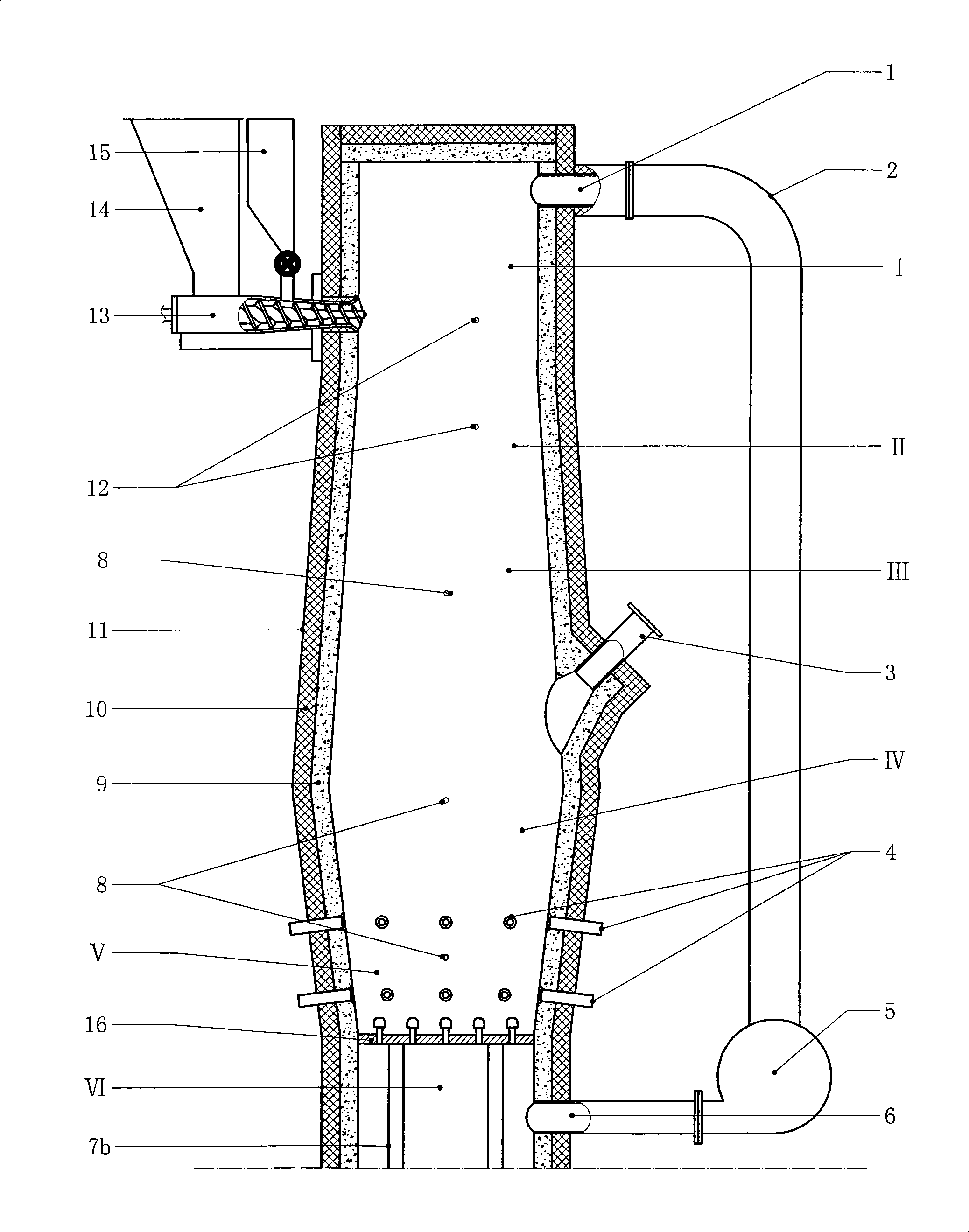
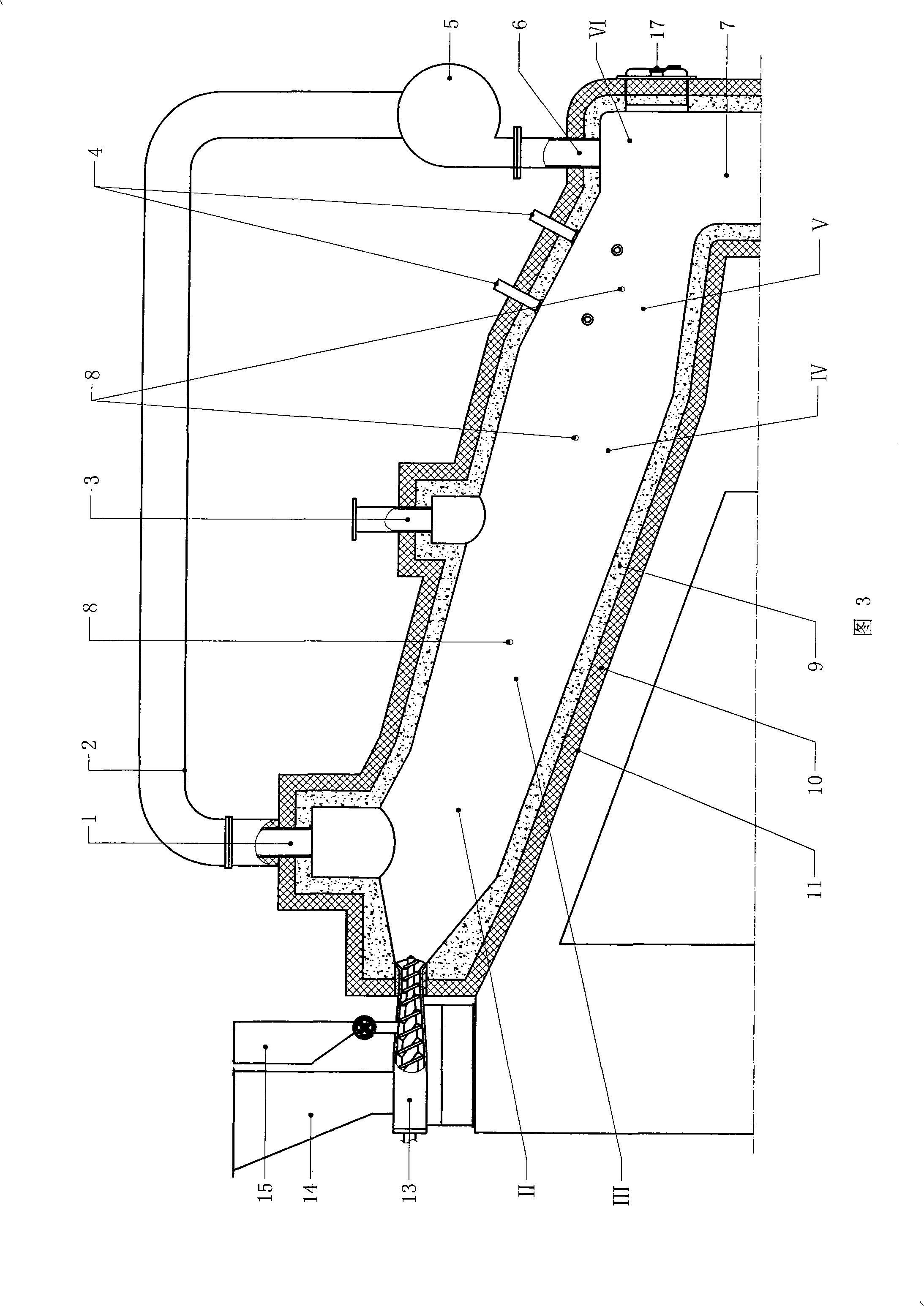
[0017] figure 1 In the shown embodiment, the gasification equipment is mainly composed of a gasification reaction furnace, a flue gas circulation air duct (2), a circulation fan (5), a plasma spray gun (4), an extrusion screw feeder (13), Garbage hopper (14) and additive hopper (15) are made up of, and wherein: gasification reaction furnace is formed blast furnace type furnace body by cylinder refractory furnace wall (9), insulation layer (10), shell (11), and refractory furnace wall ( 9) In the innermost layer, the outer layer of the refractory furnace wall (9) is the insulation layer (10), and the outer layer of the insulation layer (10) is the shell (11); Zone (I), Drying Zone (II), Pyrolysis Zone (III), Gasification Zone (IV), Burnout Zone (V) and Air Chamber (VI), Smoke Gathering Zone (I), Drying Zone ( II), the pyrolysis zone (III), the gasification zone (IV) and the burnout zone (V) are successively connected up and down, the smoke gathering zone (I) is in the upper pa...


PUM


Abstract

A plasma gasification device for converting raw garbage materials to synthetic gas with high heat value relates to a gasification process device of garbage. The device mainly comprises a gasification reaction furnace, a circular air pipe, a circular blower, a plasma burner, and a screw feeder, wherein the gasification reaction furnace is divided into a baking zone, a pyrolysis zone, a gasification zone, a burning zone and an air chamber according to operation conditions, a flue gas output port is arranged above the baking zone, a synthetic gas output port is arranged at the joint site of the pyrolysis zone and the gasification zone, and a flue gas recirculation input port is arranged inside the air chamber; and a flue gas recirculation air pipe is connected between the flue gas output port and an induced draft port of the circular blower, the air outgoing port of the circular blower is connected with the flue gas recirculation input port, a plasma spray gun is installed on the side wall of the burning zone, and the discharge port of the screw feeder protrudes from the front part of the baking zone into the furnace. The inventive device can treat garbage and convert the garage into synthetic gas with high heat value, which can be used for producing secondary clean energy products, at the same time.

Description

Technical field [0001] The invention relates to garbage treatment equipment, in particular to gasification equipment for garbage. Background technique [0002] At present, the energy shortage and the environmental protection situation are severe. With the development of my country's national economy and the continuous expansion of urban scale, garbage is increasing rapidly, and its content of harmful components is getting higher and higher. If it is not handled properly, it will pollute the environment and threaten people's health. This will not only restrict The progress of the society also affects the sustainable development of the national economy. At present, China's treatment of municipal solid waste mainly includes sanitary landfill technology, composting (biochemical) technology and incineration technology. Most areas use sanitary landfill to treat municipal solid waste, which not only takes up a lot of land, wastes resources, but also easily pollutes Land and ground...

Claims


Application Information

Patent Timeline
IPC IPC(8): C01B3/02B09B3/00
Inventor 周开根
Owner 衢州市广源生活垃圾液化技术研究所
Why Eureka
Try Eureka