Power supply system for minisize composite regenerative fuel battery

A fuel cell and power system technology, which is used in regenerative fuel cells, fuel cells, fuel cell additives, etc., can solve the problems of microporous membrane flooding, increased gas transmission resistance, etc., and achieve stable output power and cycle operation performance. good effect

Inactive Publication Date: 2008-12-17
SOUTH CHINA UNIV OF TECH
View PDF2 Cites 8 Cited by
  • Summary
  • Abstract
  • Description
  • Claims
  • Application Information

AI Technical Summary

Problems solved by technology

However, this method is prone to flooding due to the impermeability of the microporous membrane during power generation operation, and the increased microporous layer will lead to an increase in gas transmission resistance.

Method used


Image

  • Power supply system for minisize composite regenerative fuel battery
  • Power supply system for minisize composite regenerative fuel battery
  • Power supply system for minisize composite regenerative fuel battery

Examples


Embodiment 1

[0046] (1) Prepare materials and components

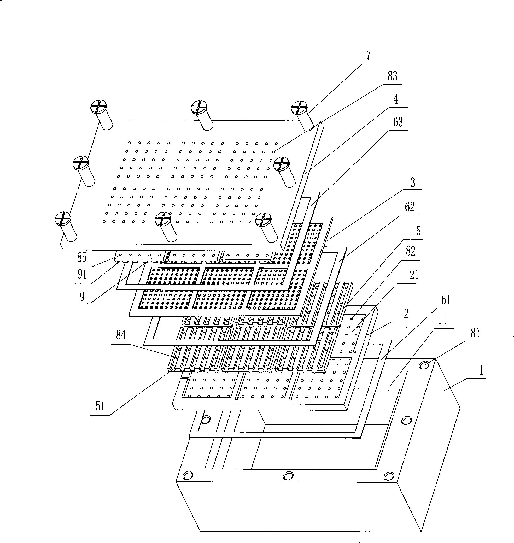
[0047] In the membrane electrode assembly shown, Nafion112 membrane is used as the proton exchange membrane, and the area of ​​a single electrode is 1cm×1cm, and the distance between them is 1mm; Johnson Matthey 40% Pt / C catalyst is used for both cathode and anode, and the anode Pt loading is 0.6mg / cm 2 , the cathode Pt loading is 0.8mg / cm 2 The hydrogen storage material uses 10 grams of LaNi5 alloy powder, uses a degreasing sponge as a water-retaining material, and adds about 10 ml of water; hydrophilic carbon paper and PTFE content without polytetrafluoroethylene (PTFE) treatment are 15% hydrophobic carbon Paper is used as the diffusion layer of the anode and cathode respectively; the anode and cathode plates are made of graphite, with a size of 1cm×1cm; thin platinum wires are used as the plate wires; the bottom box, bottom plate, and top cover are all made of organic glass materials, the size of which The membrane electrode ...

Embodiment 2

[0051] (1) Prepare materials and components

[0052] Both cathode and anode catalysts use TANAKA 50% Pt / C catalyst, and other materials and components are the same as in Example 1.

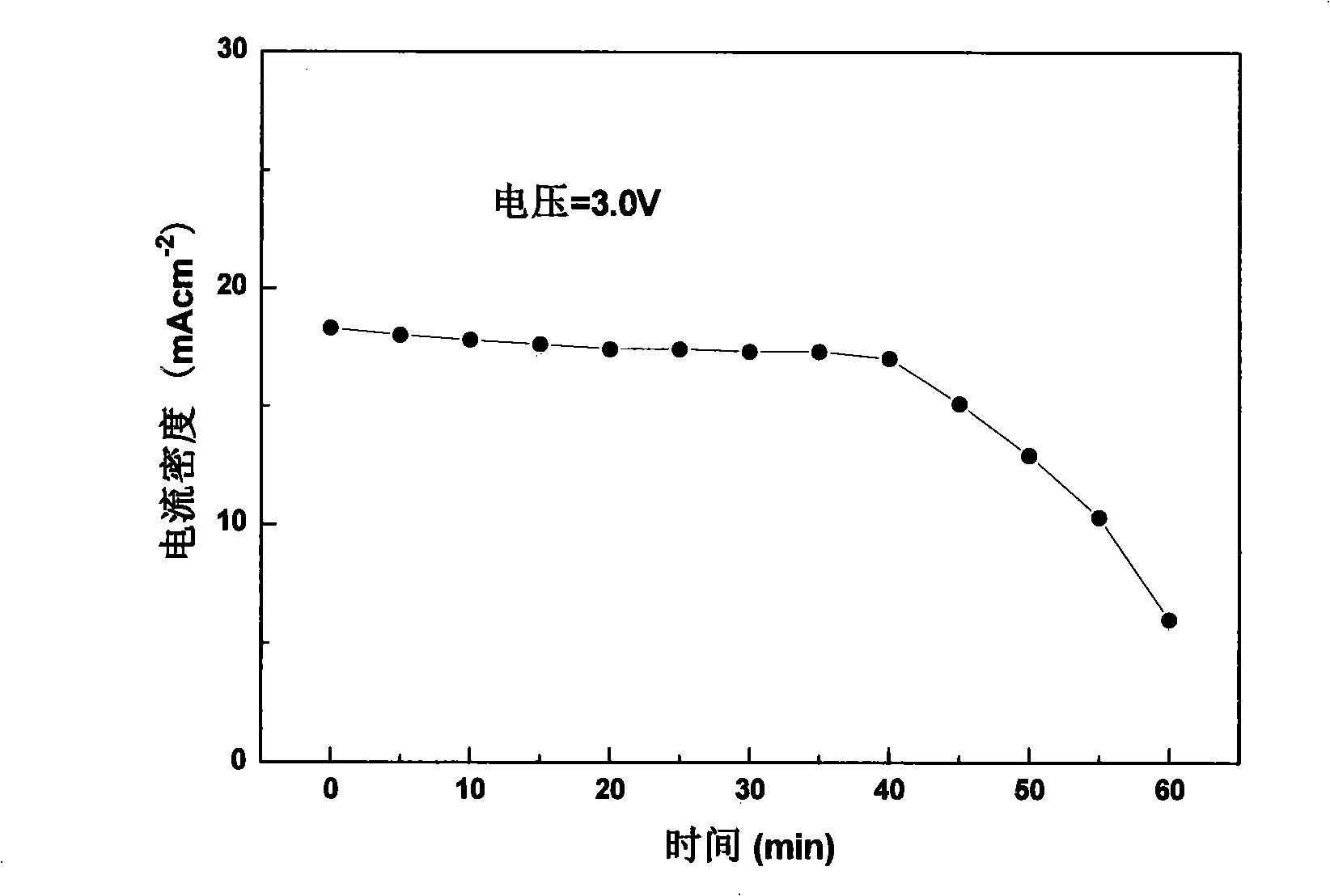
[0053] (2) Assembly test

[0054] Assembled with embodiment 1. First operate in electrolysis mode with a voltage of 9.3V for 2 hours, then switch to fuel cell mode to test its constant voltage discharge performance at 3.0V, the performance curve is as follows image 3 shown. It can be seen from the figure that at a constant voltage of 3.0V, the current density can be maintained at about 18mA cm -2 Continue to discharge for about 40 minutes.

Embodiment 3

[0056] (1) Prepare materials and components

[0057] Both cathode and anode catalysts use 20% Pt / CNT catalysts, and other materials and parts are the same as in Example 1.

[0058] (2) Assembly test

[0059] Assembled with embodiment 1. Firstly operate in electrolysis mode with a voltage of 8.6V for 2 hours, and then switch to fuel cell mode to test its temperature at 10mA cm -2 Constant current discharge performance under current density; recirculate once, test it at 20mA·cm -2 The constant current discharge performance under the current density, the performance curve is as follows Figure 4 shown. It can be seen from the figure that at 10mA·cm -2 Under the current density, it can maintain the voltage of 3.6V for about 50 minutes; at 20mA·cm -2 Under the current density, the voltage of 2.9V can be maintained for about 25 minutes.


PUM

PropertyMeasurementUnit
Thicknessaaaaaaaaaa

Abstract

The invention discloses a power supply system for a miniature combined regenerative fuel cell. The power supply system is formed by compactly pressing a proton exchange membrane which includes a plurality of membrane electrode units and serves as a dual-function membrane electrode assembly for both electrolyzation and power generation, a bottom box which is filled with hydrogen-storage materials and electrolytic water, and taken as the hydrogen storage and the water supply, a base plate with air holes, a pole plate and a top cover. The power supply system can automatically absorb oxygen as an oxidant from the air. The membrane electrode units are connected in series in a certain order, and thereby realizing the cycle operation of electrolyzation and discharge on the same membrane. Therefore, the equipment structure is simplified and the size and the weight are reduced. The power supply system has the advantages of good cycle operation performance and stable output power, and provides a good development for the application of the miniature fuel cells in the aspect of the portable electronic products.

Description

technical field [0001] The invention relates to a miniature proton exchange membrane fuel power supply system, which does not need to use an external hydrogen source, and is a combined regenerative fuel cell power supply system that realizes its "charging" and discharge through the cyclic operation of electrolyzed water and battery power generation . Background technique [0002] A fuel cell is a device that directly converts the chemical energy of fuel into electrical energy. Among them, the proton exchange membrane fuel cell (PEMFC) has become the most widely used fuel cell. When PEMFC with H 2 When used as fuel, the by-products are only heat and water, which is a very clean and efficient way of energy conversion. PEMFC also has the advantages of fast startup, room temperature operation, no electrolyte loss, long life, and high specific power, and has broad application prospects in transportation, electronics, aviation, defense and other fields. [0003] In recent year...

Claims


Application Information

Patent Timeline
IPC IPC(8): H01M8/18H01M8/10H01M8/02H01M4/86H01M4/92H01M4/90H01M8/04089H01M8/04291H01M8/1004H01M8/1007
CPCY02E60/50
Inventor 苏华能廖世军
Owner SOUTH CHINA UNIV OF TECH
Why Eureka
Try Eureka