

Chemical link coupling catalytic reforming hydrogen making method and device
A catalytic reforming and chemical chain technology, applied in chemical instruments and methods, chemical recovery, inorganic chemistry, etc., to achieve the effect of high hydrogen purity, low cost, and improved hydrogen production efficiency
- Summary
- Abstract
- Description
- Claims
- Application Information
AI Technical Summary
Problems solved by technology
Method used
Image

Examples
Embodiment 1
[0027] Below in conjunction with embodiment and accompanying drawing, content of the present invention is described in further detail:
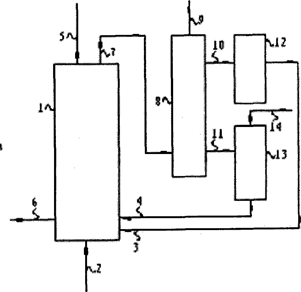
[0028] Such as figure 1 As shown, the chemical chain coupling catalytic reforming hydrogen production device used in the present invention includes a reactor 1 , a separator 8 , a catalyst regeneration device 12 , and a carbon dioxide adsorbent calcination and decomposition furnace 13 . Specifically, it can be: the space in the reactor 1 is a reaction space, and the wall of the reactor 1 is provided with a raw material feed hole 5, a catalyst feed port 3, and a carbon dioxide adsorbent feed port 4 communicating with the reaction space. , water vapor feed port 2, catalyst and carbon dioxide adsorbent discharge port 6, gas-solid mixture outlet 7; the separator 8 is connected with the gas-solid mixture outlet 7, including gas outlet 9, catalyst discharge port 10, carbon dioxide adsorption The catalyst discharge port 11, the hydrogen-containing ...
Embodiment 2
[0037] a) heating the bio-oil and steam to 200 degrees Celsius, and after adjusting the flow of steam to make the water-carbon ratio in the reactor 5.0, send them into reactor 1, and the temperature of reactor 1 is 450 degrees Celsius;
[0038] B) the mixed gas fully contacts with the rhodium-based catalyst and calcium oxide in the reactor 1, and reacts to generate a hydrogen-containing mixed gas;
[0039] c) The hydrogen-containing gas coming out from the reactor 1 and the rhodium-based catalyst, calcium carbonate and other gas-solid mixtures enter the separator 8 for separation, and the separated hydrogen-containing gas is industrially processed to finally obtain hydrogen with a purity of 99.9%, bio-oil The conversion rate is 60%;
[0040] d) The rhodium-based catalyst separated from the separator 8 enters the regeneration unit 12, and after being reduced at 400 degrees Celsius, it is reactivated, and then sent back to the reactor 1;
Embodiment 3
[0044] a) Naphtha and steam are heated to 300 degrees Celsius, and after the water-carbon ratio in the reactor is 10.0 by adjusting the steam flow rate, they are sent into reactor 1, and the temperature of reactor 1 is 600 degrees Celsius;
[0045] b) The mixed gas is in full contact with the cobalt-nickel catalyst in the reactor 1 and the molarite, and the reaction generates a hydrogen-containing mixed gas;
[0046] c) The hydrogen-containing gas coming out from the reactor 1 and the gas-solid mixture such as cobalt-nickel-based catalyst and calcium carbonate enter the separator 8 for separation, and the separated hydrogen-containing gas is industrially processed to finally obtain hydrogen with a purity of 99.9%. Naphtha conversion rate is 75%;
[0047] d) The cobalt-nickel-based catalyst separated from the separator 8 enters the regeneration device 12, and after being reduced at 400 degrees Celsius, it is reactivated, and then sent back to the reactor 1;
[0048] e) The calci...
PUM
 Abstract
Description
Claims
Application Information