
Novel acoustical-electrical converter and microphone

An acousto-electric converter and microphone technology, applied in piezoelectric/electrostrictive transducer microphones, piezoelectric/electrostrictive transducers, sensors, etc., can solve the difficulty of parts processing and the improvement of assembly accuracy, and the volume of the microphone. It is impossible to achieve small problems, performance and structural bottlenecks, etc., to achieve the effect of simplifying the manufacturing process, reducing the number of parts, and low manufacturing costs.

Inactive Publication Date: 2009-11-25
SHENZHEN HORN AUDIO
View PDF2 Cites 11 Cited by
  • Summary
  • Abstract
  • Description
  • Claims
  • Application Information

AI Technical Summary

Problems solved by technology

Under the trend of more and more miniaturization of contemporary portable equipment, the processing difficulty and assembly accuracy of parts have been greatly improved, and even reached a performance and structural bottleneck; Reliability is also questioned
For the microphone, the electret condenser structure requires a large air resonant cavity, and the volume of the microphone cannot be made small; and the electroacoustic performance of the microphone such as sensitivity is affected by the stability of the electret charge and the air resonant cavity, etc. The impact of the acoustic structure creates a natural bottleneck for performance improvement

Method used


Image

  • Novel acoustical-electrical converter and microphone
  • Novel acoustical-electrical converter and microphone
  • Novel acoustical-electrical converter and microphone

Examples


specific Embodiment approach 1

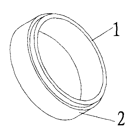
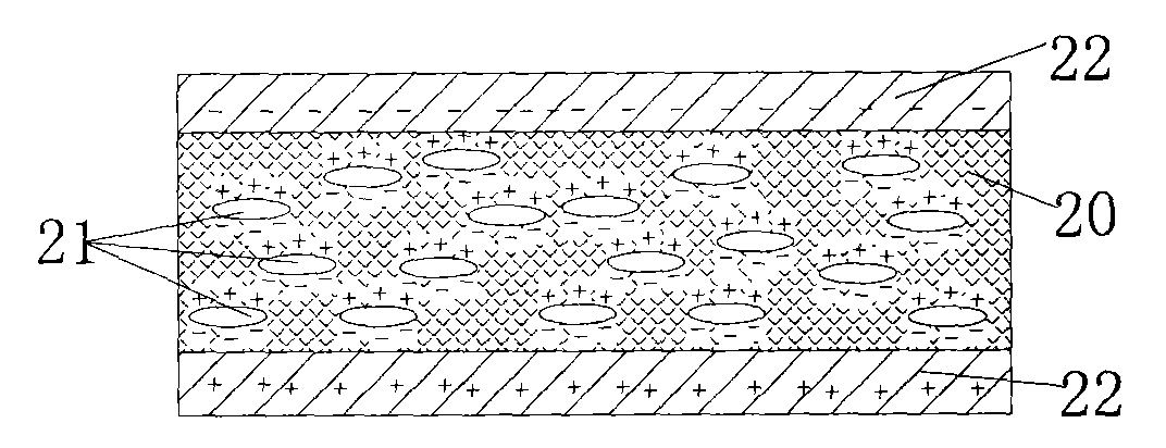
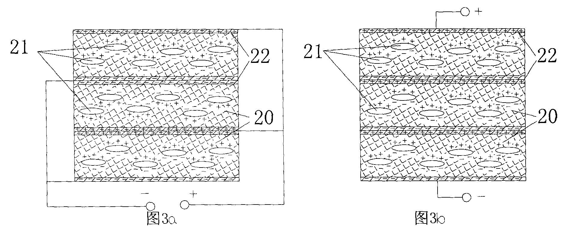
[0033] The acoustic-electric transducer of this specific embodiment is as figure 1 As shown, it includes a copper ring 1 and an acoustic-electric conversion unit. The acoustic-electric conversion unit is a piezoelectric film 2 wound on the periphery of the copper ring 1, and the number of wound layers is one or more than one. The piezoelectric film 2 is made by cutting a porous polymer piezoelectric film, and its structure is as follows: figure 2 As shown, it includes a porous polymer piezoelectric film 20 and a metal layer 22 covering the porous polymer piezoelectric film 20 . The porous polymer piezoelectric film 20 contains a plurality of closed pore structures 21 , and one end of each pore structure 21 close to the upper surface of the porous polymer piezoelectric film 20 is positively charged, and one end close to the lower surface is negatively charged. The metal layer 22 is a layer of metal evaporated on the upper and lower surfaces of the porous polymer piezoelectri...

specific Embodiment approach 2

[0048] The micro-acoustoelectric conversion device of this specific embodiment, such as Figure 5 As shown, it includes: a tube core 15 and an acoustic-electric conversion unit, the acoustic-electric conversion unit is used for converting sound signals into electrical signals, and the tube core 15 is used for primary amplification of the electrical signals. The die 15 has a gate 16 serving as a signal input, a signal output 18 for outputting a signal, and a ground 17 . The acoustic-electric conversion unit is a piezoelectric film 2 wound around the die 15 . One side of the piezoelectric film 2 is signal-connected to the gate 16 , and the other side is signal-connected to the ground terminal 17 . In this specific embodiment, the outer surface of the piezoelectric film 2 is connected to the ground terminal 17 of the die 15 through the ground connector 14 .

[0049] When external sound waves act on the piezoelectric film, the piezoelectric film generates charges between the upp...

specific Embodiment approach 3

[0050] Traditional remote control such as Image 6 As shown, it includes a wire rod and a wire control box 33 somewhere in the wire rod. The microphone 32 is arranged in the wire control box 33 . The wire includes at least one ground wire 30 and one signal wire 31 arranged in parallel. The microphone 32 is electrically connected to the ground line 30 and the signal line 31 , respectively.

[0051] The flexible acoustic-electric transducer of this specific embodiment, such as Figure 7 with Figure 8 As shown, including: wire and sound-electric conversion unit. Wherein the wire includes at least one signal line 31 and one grounding line 30 arranged in parallel, and there is an insulating material between the signal line and the grounding line to keep the insulation between the two; and the acoustic-electric conversion unit includes a grounding ring 34 and a voltage Electrofilm 2. The piezoelectric film 2 is wound around the periphery of the wire, and the portion of the si...


PUM


Abstract

The invention discloses a novel acoustical-electrical converter and a microphone. The microphone comprises a shell, a circuit board assembly and an acoustical-electrical converter. The acoustical-electrical converter comprises a base material and an acoustical-electrical converting unit, and the acoustical-electrical converting unit is a piezoelectric film winded round the base material. The piezoelectric film comprises a porous polymer thin film and metal layers, wherein the porous polymer thin film is provided with a plurality of air bubbles with both electric ends, and a plurality of equivalent heterogeneous charges are bound in an upper medium surface layer and a lower medium surface layer of the porous polymer thin film and point to the upper surface and the lower surface of the porous polymer thin film; the metal layers are plated at the upper surface and the lower surface of the porous polymer thin film in a steaming way; and the piezoelectric film is wound round the base material by one layer or more. The acoustical-electrical converter and the microphone of the technical scheme of the invention have a higher piezoelectric coefficient and charge stability because of takingthe porous polymer piezoelectric thin film as the acoustical-electrical converting unit, are easy to meet the application requirement of small size and have the advantages of smaller thickness, less part number, simple manufacturing technology, low cost, wide material resources and low material cost.

Description

technical field [0001] The invention relates to the technical field of acoustic energy conversion, in particular to a novel acoustic-electric transducer and a microphone. Background technique [0002] A microphone is a transducer device that converts an acoustic signal into an electrical signal, and its core is an acoustic-electric converter. In the current field of electro-acoustics, microphones and speakers mostly adopt capacitive or dynamic structures, and typical examples are electret condenser microphones and dynamic speakers. The parts of these two structures require precision machining, and the tolerance fit during assembly is also required to be very strict. Under the trend of more and more miniaturization of contemporary portable equipment, the processing difficulty and assembly accuracy of parts have been greatly improved, and even reached a performance and structural bottleneck; Reliability has also been questioned. For the microphone, the electret condenser st...

Claims


Application Information

Patent Timeline
IPC IPC(8): H04R17/00H04R17/02
Inventor 吴宗汉欧阳小禾
Owner SHENZHEN HORN AUDIO
Learn More