
Method for processing lithium niobate or lithium tantalate wafer

A technology of lithium tantalate and lithium niobate, applied in the field of processing lithium niobate or lithium tantalate wafers, can solve the problems of hydrogen explosion, difference in reduction degree of wafers, depolarization, etc. The effect of weakening the effect and increasing the conductivity

Active Publication Date: 2009-12-23
CETC DEQING HUAYING ELECTRONICS +1
View PDF4 Cites 26 Cited by
  • Summary
  • Abstract
  • Description
  • Claims
  • Application Information

AI Technical Summary

Problems solved by technology

U.S. Patent US6319430 proposes a method for high-temperature heat treatment of LN and LT wafers in a fluid reducing atmosphere composed of nitrogen and hydrogen. This process has high efficiency, but the hydrogen used in the reduction process is likely to cause explosion hazards, so the requirements for equipment are relatively high. High, and for LT, high temperature heat treatment is also prone to depolarization
Japanese patent JP2004-002853 and Korean patent KR20040034230 both propose a method of performing high-temperature deep reduction treatment on LT wafers in a circulating reducing gas or inert gas, and then alternately stacking these wafers with target wafers to be processed for heat treatment. This process is not simple enough, and there may be some differences in the degree of wafer reduction
U.S. Patent US20050269516 proposed a method of coating lithium carbonate, magnesium carbonate, calcium carbonate, lithium hydride, calcium hydride and other reducing substances on the surface of LN and LT wafers, and then in a vacuum or reducing atmosphere, at a temperature higher than 250 ° C The method of heat treatment at the temperature inside the point, this method has more process steps, the reducing ability of the selected reducing substance carbonate is weak, the required heat treatment temperature may be higher, and these substances may decompose and generate gas, May have significant impact on device and chip performance

Method used


Image

  • Method for processing lithium niobate or lithium tantalate wafer
  • Method for processing lithium niobate or lithium tantalate wafer
  • Method for processing lithium niobate or lithium tantalate wafer

Examples


Embodiment 1

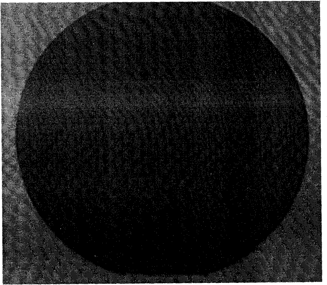
[0017] First the lithium niobate wafer to be processed is placed in a corundum crucible suitable for the wafer size, and iron powder and lithium carbonate powder (the mass ratio of iron powder in the mixed system is 5% in the mixed system, wherein lithium carbonate The purity of the corundum powder is 4N, and the specification of iron powder is 500 mesh), and then the corundum crucible is placed in a heat treatment furnace, and the temperature is raised to a holding temperature of 450°C under a nitrogen atmosphere with a flow rate of 0.5L / min. Heat treatment at lower temperature for 3 hours, then lower to room temperature and take out the wafer. The prepared lithium niobate wafer is gray, as figure 1 Shown; volume resistivity at 10 12 Ω·cm order of magnitude.

Embodiment 2

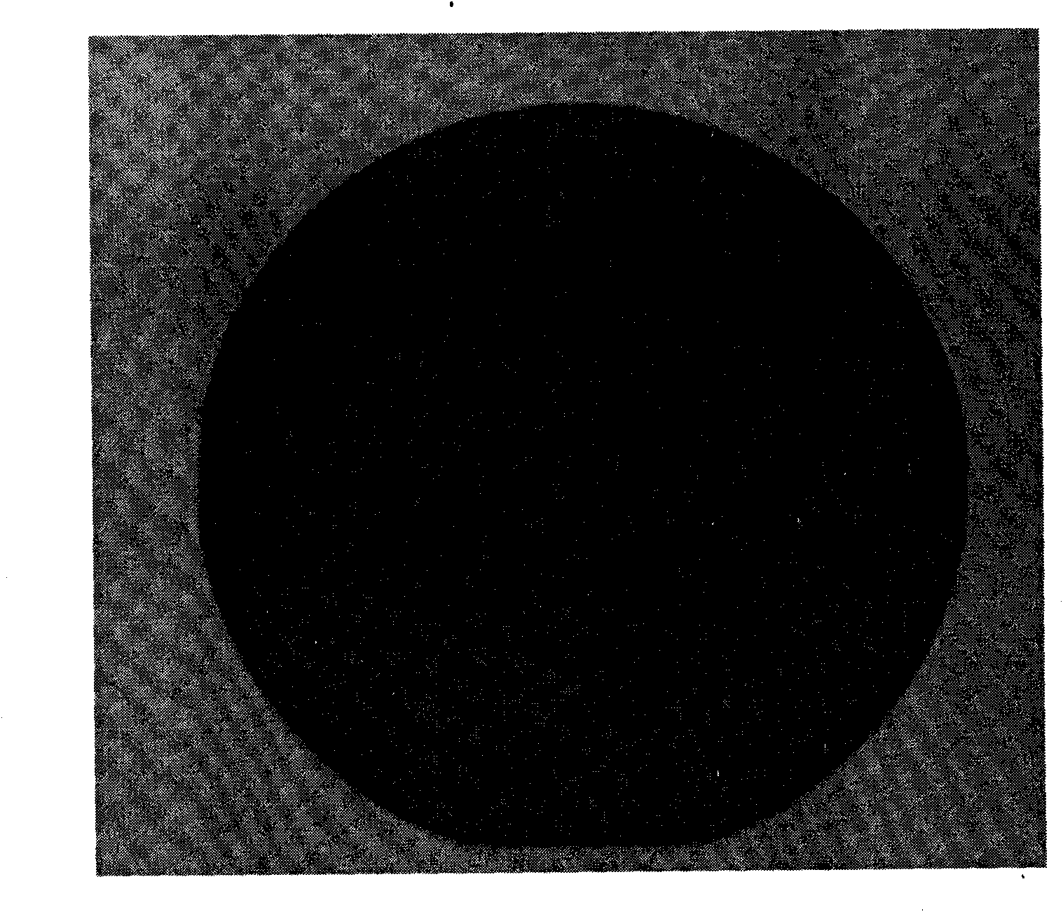
[0019] First the lithium niobate wafer to be processed is placed in a corundum crucible suitable for the wafer size, and iron powder and lithium carbonate powder (the mass ratio of iron powder in the mixed system is 6% in the mixed system, wherein lithium carbonate The purity of the corundum powder is 4N, and the specification of iron powder is 500 meshes) into the crucible to completely cover the wafer, then place the corundum crucible in a heat treatment furnace, and raise the temperature to a holding temperature of 480°C under a nitrogen atmosphere with a flow rate of 0.6L / min Heat treatment at lower temperature for 5 hours, then drop to room temperature and take out the wafer. The prepared lithium niobate wafer was dark gray, as figure 2 Shown; volume resistivity at 10 11 Ω·cm order of magnitude.

Embodiment 3

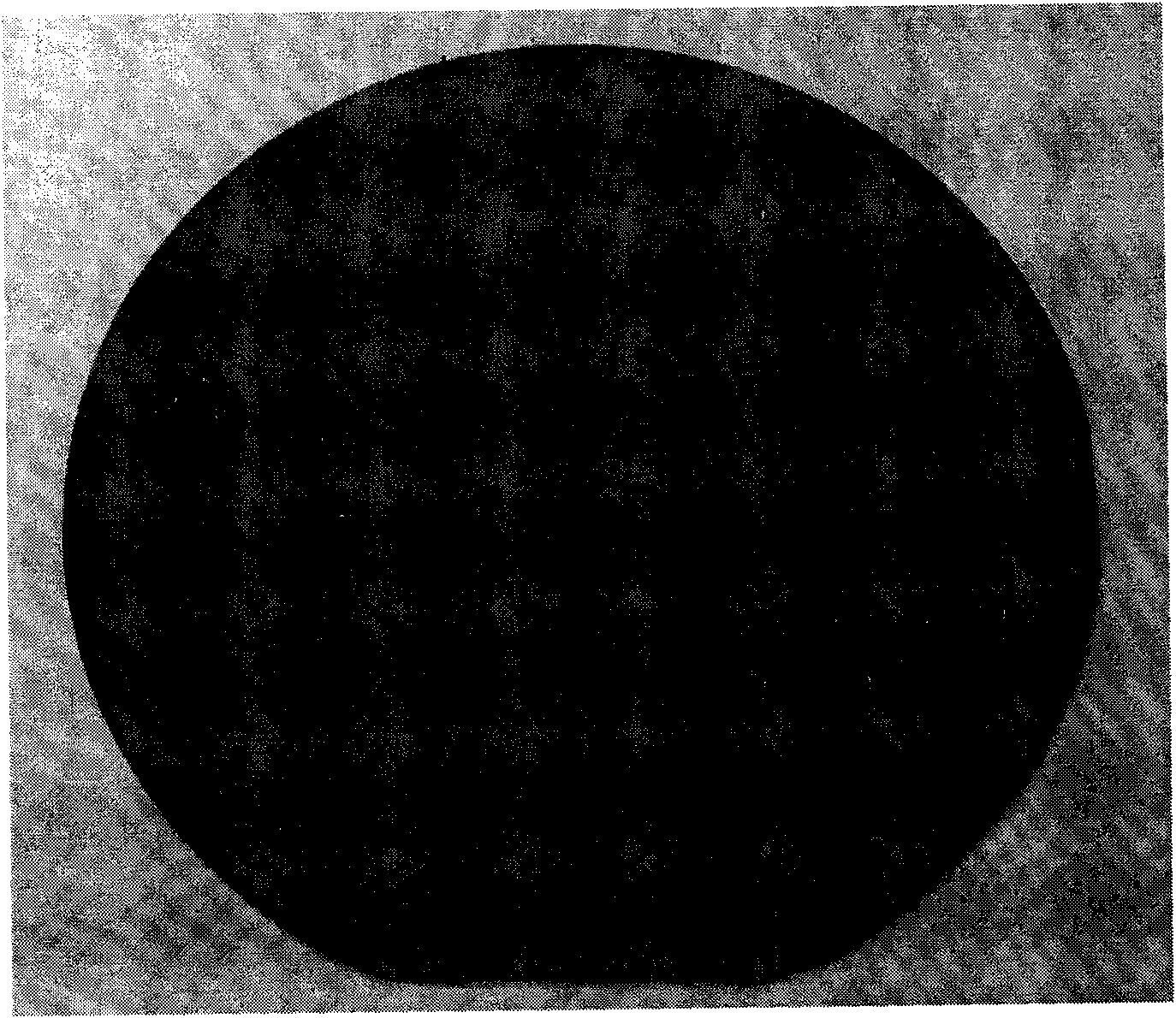
[0021] First the lithium niobate wafer to be processed is placed in a corundum crucible suitable for the wafer size, and iron powder and lithium carbonate powder (the mass ratio of iron powder in the mixed system is 8% in the mixed system, wherein lithium carbonate The purity of the corundum powder is 4N, and the specification of the iron powder is 500 mesh) into the crucible to completely cover the wafer, then place the corundum crucible in a heat treatment furnace, and raise the temperature to a holding temperature of 510°C under a nitrogen atmosphere with a flow rate of 0.8L / min Heat treatment under lower temperature for 8 hours, then drop to room temperature and take out the wafer. The prepared lithium niobate wafers appear black, such as image 3 Shown; volume resistivity at 10 10 Ω·cm order of magnitude.


PUM

PropertyMeasurementUnit
Volume resistivityaaaaaaaaaa

Abstract

The invention discloses a method for processing a lithium niobate or lithium tantalate wafer, which comprises the following steps: respectively placing the lithium niobate or lithium tantalate wafer to be processed into a crucible; adding iron powder and lithium carbonate powder evenly mixed in advance according to mass proportion to completely cover the wafer; placing a corundum crucible into a thermal treatment furnace; performing thermal treatment for 3-20 hours at 450-550 DEG C under the nitrogen atmosphere with the flow rate of 0.5-1L / min to prepare a finished product of the lithium niobate or lithium tantalate wafer. The wafer resistivity is at the magnitude order of between 10 and 10, compared with the conventional non-processed wafer, the resistivity is greatly reduced, the method can effectively prepare a wafer needed for a SAW device through the thermal treatment in a short time, and increase a finished product ratio in the manufacture process of an element, therefore, the method for processing lithium niobate or lithium tantalite wafer becomes an industrialized optimizing method.

Description

(1) Technical field [0001] The invention relates to a method for processing lithium niobate or lithium tantalate wafers, belonging to the technical field of crystal materials. (2) Background technology [0002] Lithium niobate (LiNbO 3 , LN) and lithium tantalate (LiTaO 3 , LT) crystal is a typical multifunctional material, which integrates various excellent properties such as piezoelectric, ferroelectric, pyroelectric, acousto-optic, electro-optic, nonlinear and photorefractive, etc., in surface acoustic wave (SAW) devices, It is widely used in the fields of optical communication, laser and optoelectronics. Lithium niobate and lithium tantalate are used to make surface acoustic wave devices due to their comprehensive properties such as good piezoelectric effect, electromechanical coupling, temperature coefficient and low insertion loss, and are used in many high-end devices such as mobile phones, satellite communications, and aerospace. communication field. In industry,...

Claims


Application Information

Patent Timeline
IPC IPC(8): C30B33/02C30B29/30
Inventor 夏宗仁吴剑波颜涛崔坤秦小勇王继杨刘宏张明凤朱怀烈
Owner CETC DEQING HUAYING ELECTRONICS
Learn More