Optical system of scattering-type cloud particle detector

An optical system and cloud particle technology, applied in scattering characteristic measurement, optics, optical components, etc., can solve the problems of unfavorable optical system design, processing, loss of scattered light, attenuation of scattered light, etc., to solve the problem of uneven lighting, The same time width, the effect of solving the diffraction problem

Inactive Publication Date: 2010-01-20
CHANGSHU NANJING NORMAL UNIV DEV RES INST
View PDF0 Cites 25 Cited by
  • Summary
  • Abstract
  • Description
  • Claims
  • Application Information

AI Technical Summary

Problems solved by technology

(1) The system uses semiconductor lasers output in free space. In the process of light transmission, there are fast axis and slow axis. After a certain distance, the light spot is elliptical. Design, processing, and processing of the subsequent optical system; (2) The 200×180um beam in the system is formed by an aperture. Since the aperture of the aperture is very small, diffraction in wave optics must be considered. Therefore, after the laser reaches the optical absorber , its size is far more than the size of 200um×180um, because the particle scattering energy itself is very small, the direct light must be highly suppressed, increasing the area of ​​the mirror can increase the degree of suppression of direct light, but at the same time it also loses the scattered light, and it is 0 The scattered light in the vicinity of ° makes the scattered light greatly attenuated; (3) the direct light total reflection mirror cannot use the adjustment frame (for fear of blocking the scattered light), so it is directly glued on the scattered light collecting lens; (4) the receiving There is no narrow-band filter in the system, and cloud particle detection is generally carried out during the day, and a lot of stray light enters the receiving system, which affects the signal-to-noise ratio of the system; (5) The system can only obtain the size information of cloud particles, but cannot obtain cloud particle phase

Method used


Image

  • Optical system of scattering-type cloud particle detector

Examples


Embodiment Construction

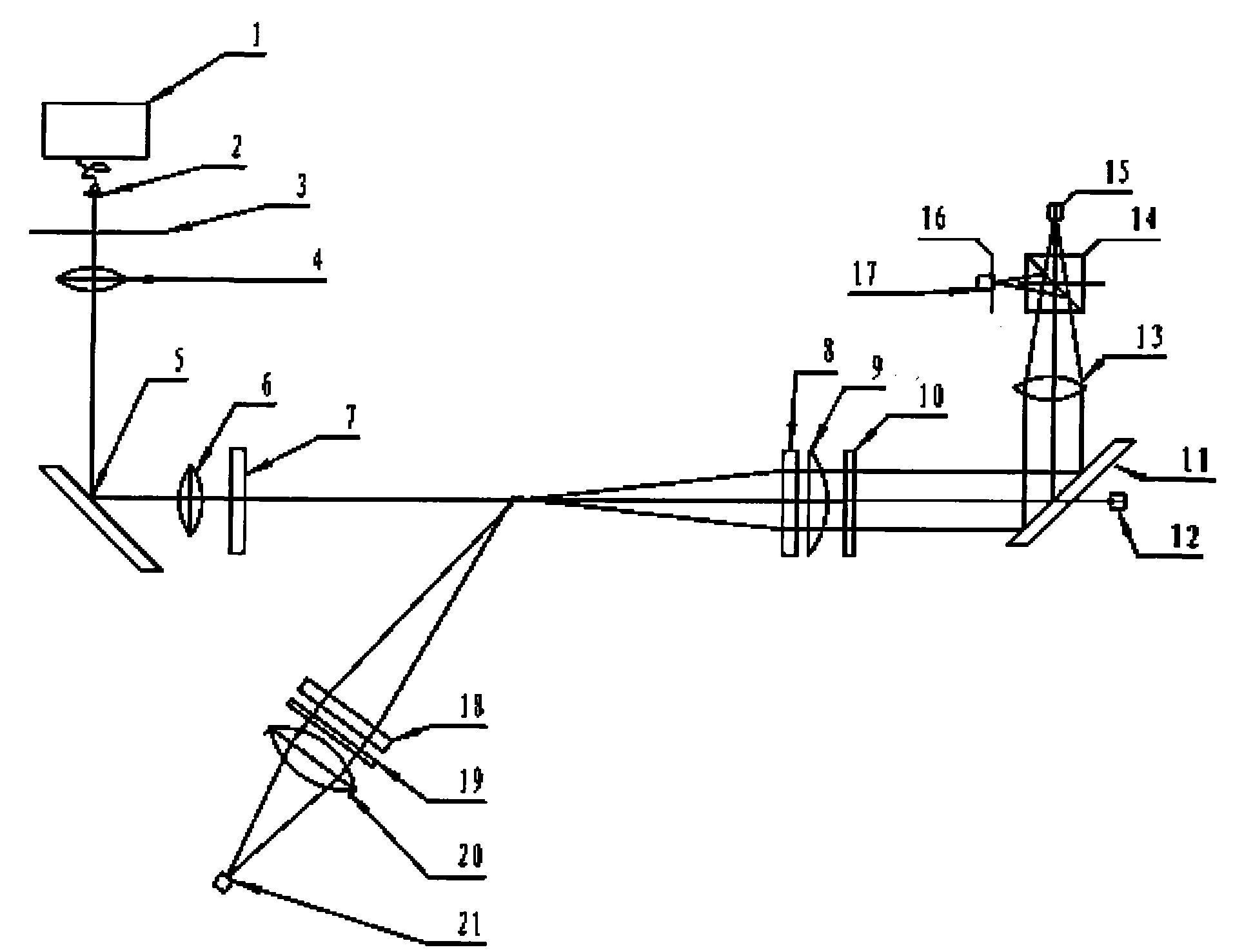
[0042] like figure 1 As shown, the present invention is a scattering cloud particle detector based on a novel optical path, which uses a single-mode optical fiber to couple and output a semiconductor laser as an illumination light source, and uses an aspheric collimator to collimate the laser light; using a square aperture diaphragm and a 4f transformation system, It not only produces the required uniform illumination of the laser light, but also solves the diffraction problem in the beam cutting process, and improves the purity of scattered light reception; when receiving scattered light, a narrow-band filter is used to improve the signal-to-noise ratio of the instrument during daytime work; The cloud particle detector invented has two receiving angles, not only can obtain the size of cloud particles, but also can infer the phase state of cloud particles according to the ratio of the scattering intensity of the two angles.

[0043] The system consists of a single-mode fiber c...


PUM

PropertyMeasurementUnit
diameteraaaaaaaaaa
refractive indexaaaaaaaaaa

Abstract

The invention discloses a scattering multi-angle receiving optical system of a scattering-type cloud particle detector based on a single-mode fiber coupling output semi-conductor laser. The optical system of the scattering-type cloud particle detector comprises a transmitting optical unit, a forwards scattering detection unit and a side backward scattering detection unit and uses the single-mode fiber coupling output semi-conductor laser, an aspherical collimating mirror, a square-hole diaphragm and a 4f transformation system so as to not only generate the uniform illumination of needed laser, but also solve the diffraction problem in a beam-cutting process and improve the purity of received scattered light. The cloud particle detector of the invention has two receiving angles and can deduce the phase states of cloud particles according to a ratio of the two electric signals output at the two angles.

Description

technical field [0001] The invention designs a cloud particle detector based on a single-mode optical fiber coupling output semiconductor laser and scattering multi-angle reception. Develop a cloud particle detector using a single-mode fiber-coupled output semiconductor laser and a square hole diaphragm. By using a square hole to cut off the edge of the Gaussian beam, only the top of the Gaussian beam remains, and use a 4f optical system to image the square hole at the center of the measurement sensitive area. , to generate an approximate flat-top beam at the center of the measurement sensitive area, to solve the problem of uneven illumination, to use a square hole diaphragm to generate a square beam, so that the time for particles to pass through the illuminated area is the same, and the time width of the electric pulse is the same, which is easy for subsequent electronic processing . The cloud particle detector invented has two scattering energy receiving systems, which rec...

Claims


Application Information

Patent Timeline
Patent Type & Authority Applications(China)
IPC IPC(8): G01N21/49G02B27/42
Inventor 卜令兵黄兴友
Owner CHANGSHU NANJING NORMAL UNIV DEV RES INST
Why Eureka
Try Eureka