

Sintering ore cooling waste gas full combustion-supporting generating set
A technology of power generation device and sintering ore, which is applied in the direction of steam engine device, machine/engine, mechanical equipment, etc., can solve the problems of low thermal cycle efficiency, high failure rate of low pressure system, high exhaust gas temperature, etc., and achieve the improvement and reduction of waste heat recovery rate Operating costs and the effect of saving land resources
- Summary
- Abstract
- Description
- Claims
- Application Information
AI Technical Summary
Problems solved by technology
Method used
Image

Examples
Embodiment Construction
[0026] The present invention will be described in detail below in conjunction with the accompanying drawings and embodiments.
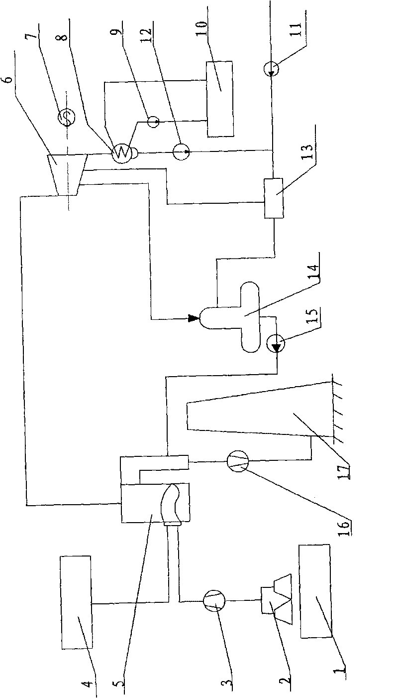
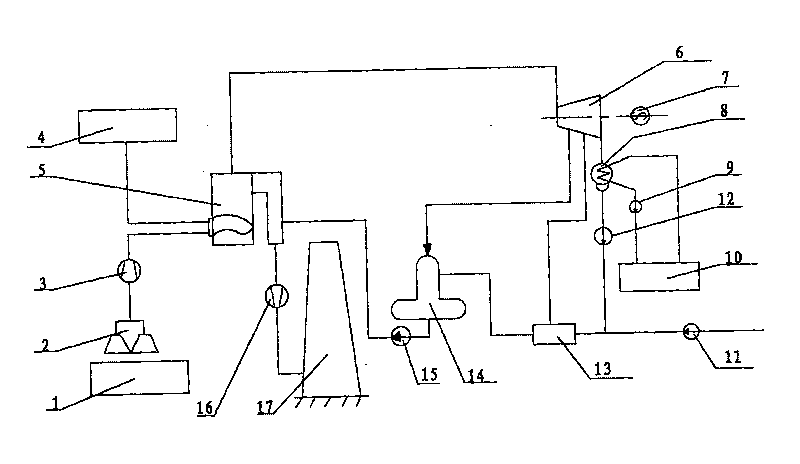
[0027] see figure 1 , a sinter cooling exhaust gas full combustion-supporting power generation device is composed of a conventional fuel boiler power generation system and a sinter cooling exhaust gas collection system.
[0028] Conventional fuel boiler power generation system consists of fuel supply system 4, power generation boiler 5, steam turbine 6, generator 7, condenser 8, circulating water pump 9, cooling tower 10, water supply pump 11, condensate pump 12, low pressure heater 13, Oxygenator 14, feedwater pump 15, induced draft fan 16, chimney 17 constitute.
[0029] The sinter cooling exhaust gas collection system consists of a sintering machine 1, an exhaust gas collector 2, and an exhaust gas pressurizer 3.
[0030] In this device, the waste gas collector 2 is placed above the sintering machine 1, and its waste gas output pipe is connected ...
PUM
 Abstract
Description
Claims
Application Information