

Gas purification method
A refining method and gas technology, applied in separation methods, gas treatment, chemical instruments and methods, etc., and can solve problems such as non-disclosure
- Summary
- Abstract
- Description
- Claims
- Application Information
AI Technical Summary
Problems solved by technology
Method used
Image

Examples
Embodiment 1
[0054] (Example 1) Gas purification containing high-concentration impurities
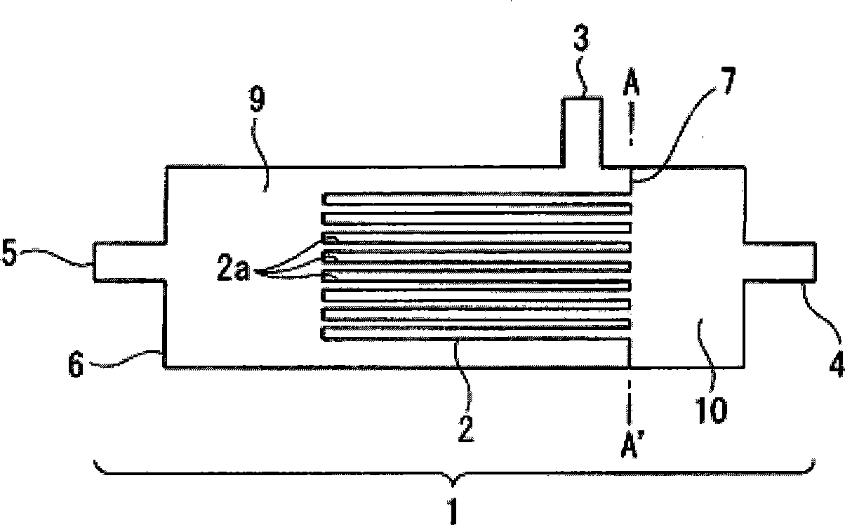
[0055] In Example 1, using figure 1 The carbon membrane module shown is used for the purification of gases containing high concentrations of impurities. The specifications of carbon membrane modules are as follows. Outer diameter of hollow filamentary carbon membrane tube: 0.525mm, length of hollow filamentary carbon membrane tube: 85mm, number of hollow filamentary carbon membrane tubes: 13, total surface area of hollow filamentary carbon membrane tube: 18.22cm 2 . The hollow-fiber carbon membrane is produced by forming and carbonizing an organic polymer membrane made of polyimide (aromatic polyimide) as a raw material.
[0056] The carbon membrane module was maintained at 25°C, and the supply gas pressure was set to 0.5 MPaG with a back pressure regulator at the non-permeated gas outlet.
[0057] (a) A gas mixed with 500 sccm of ammonia gas and 500 sccm of impurity hydrogen was supplied to t...
Embodiment 2
[0064] (Example 2) Gas purification containing low-concentration impurities
[0065] In Example 2, using figure 1 The carbon membrane module shown, refines a gas containing low levels of impurities. The specifications of carbon membrane modules are as follows. Outer diameter of hollow filamentary carbon membrane tube: 0.39mm, length of hollow filamentary carbon membrane tube: 117mm, quantity of hollow filamentary carbon membrane tube: 38 pieces, total surface area of hollow filamentary carbon membrane tube: 54.9cm 2 . The hollow-fiber carbon membrane is produced by forming an organic polymer membrane made of polyphenylene oxide (PPO) and carbonizing it after heat treatment.
[0066] The carbon membrane module was maintained at 70°C, and the supply gas pressure was set to 0.45 MPaG with a back pressure regulator at the non-permeated gas outlet.
[0067] (a) A gas containing 50 sccm of impurity hydrogen (14390 ppb) / helium mixed with 450 sccm of ammonia gas was supplied to ...
Embodiment 3
[0075] (Example 3) Gas purification containing low-concentration impurities
[0076] In Example 3, using figure 1 The carbon membrane module shown, refines a gas containing low levels of impurities. The specifications of carbon membrane modules are as follows. Outer diameter of hollow filamentary carbon membrane tube: 0.20mm, length of hollow filamentary carbon membrane tube: 120mm, quantity of hollow filamentary carbon membrane tube: 100 pieces, total surface area of hollow filamentary carbon membrane tube: 76.9cm 2 . The hollow-fiber carbon membrane is produced by forming an organic polymer membrane made of polyphenylene oxide (PPO) and carbonizing it after heat treatment.
[0077] The carbon membrane module was maintained at 30°C, and the supply gas pressure was set to 0.45 MPaG with a back pressure regulator at the non-permeated gas outlet.
[0078] A gas mixed with 200 sccm of hydrogen (9550 ppb), nitrogen (9700 ppb), methane (9200 ppb), carbon monoxide (9380 ppb) / h...
PUM
| Property | Measurement | Unit |
|---|---|---|
| length | aaaaa | aaaaa |
| total surface area | aaaaa | aaaaa |
| length | aaaaa | aaaaa |
Abstract
Description
Claims
Application Information