
Method and device for vacuum ultraviolet laser cleaning first mirror of tokamak

A vacuum ultraviolet and laser cleaning technology, which is applied to cleaning methods and appliances, chemical instruments and methods, etc., can solve problems such as unsatisfactory cleaning efficiency, affecting device operation, and difficult optical analysis, so as to facilitate the operation of automated equipment, easy collection, Mechanism obvious effect

Inactive Publication Date: 2014-10-22
DALIAN UNIV OF TECH
View PDF10 Cites 0 Cited by
  • Summary
  • Abstract
  • Description
  • Claims
  • Application Information

AI Technical Summary

Problems solved by technology

However, the application of these cleaning techniques is very limited during the cleaning of the contaminated first mirror in the magnetic confinement fusion experiment.
During the cleaning process of the mechanical cleaning method, it is easy to produce scratches on the surface of the first mirror sample. It can be observed through atomic force microscopy and other means that the depth of these scratches may reach tens of nanometers. This damage is obviously irreversible. The cleaning efficiency of some special-shaped first-mirror samples is even less ideal
Chemical cleaning and ultrasonic cleaning will more or less introduce new impurities, and the cleaning effect is not ideal. Due to the limitations of the method itself, these two cleaning methods are not locally controllable during the cleaning process
When the nuclear fusion device is running, the temperature in the cavity is very high. The impurities introduced by the chemical cleaning method and the ultrasonic cleaning method are easy to evaporate, and new impurities are introduced into the discharge chamber of the entire controllable nuclear fusion device, which makes the already complicated optical analysis. become more difficult, and in severe cases may affect the operation of the entire device

Method used


Image

  • Method and device for vacuum ultraviolet laser cleaning first mirror of tokamak
  • Method and device for vacuum ultraviolet laser cleaning first mirror of tokamak
  • Method and device for vacuum ultraviolet laser cleaning first mirror of tokamak

Examples


specific Embodiment

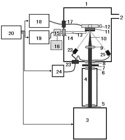
[0048] Specific examples: such as figure 1 As shown, the system involved in this method consists of a cleaning laser system, a first mirror feeding system, an air blowing system, a detection system, a control system and a frame.

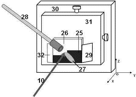
[0049] The method is as follows: the laser light output by the argon fluoride excimer laser 3 enters the sealed optical cavity 4 filled with nitrogen through the quartz window 5 to propagate, so as to avoid the energy dissipation of the excimer laser beam, and then transmits it from the quartz window 6 on the other side of the sealed optical cavity. Emitted, through the adjustable diaphragm 7, the quartz window 8 of the vacuum chamber enters the vacuum chamber 1, and finally is focused by the focusing lens 9 and directly loaded on the surface of the dust layer of the first mirror 11 installed on the workbench 12. A dust impurity layer with a thickness of about 1 micron has been deposited on the surface of the first mirror 11 during the operation of t...


PUM


Abstract

The invention discloses a method and a device for cleaning a tokamak first mirror by vacuum ultraviolet laser. A dust impurity deposit layer on the first mirror is cleaned by adopting a laser ablation method; through controlling the output energy of a laser device, the energy density of an excimer laser bundle on the surface of a first mirror surface is at a cleaning threshold of the impurity deposition layer and the damages threshold of first mirror metal, and the first mirror metal material can not be damaged when the impurity is cleaned simultaneously. A laser with 193nm wavelength is adopted for the method and the device for cleaning the tokamak first mirror by the vacuum ultraviolet laser, in the mutual effect process of the laser and the material, the ablation effect is less, the surface uniformity is good, the dust is cleaned, and the effect is ideal.

Description

technical field [0001] The invention relates to the field of magnetic confinement fusion devices. During the operation of the magnetic confinement fusion device, some impurities are easily deposited on the surface of the first mirror to form a dust impurity layer, which affects the normal operation of optical diagnostic equipment. In particular, the invention relates to a method and equipment for quickly removing the dust impurity layer deposited on the surface of the first mirror of the Tokamak and restoring the reflectivity of the mirror without introducing new impurities. Background technique [0002] In the study of magnetic confinement fusion, ultraviolet, visible light, infrared and other diagnostic systems will observe the plasma through the first mirror. The mirrors used for these plasma diagnosis must be installed in the vacuum chamber and directly face the plasma. Optical diagnostics require the mirror to have a relatively wide viewing angle, so the first mirror ha...

Claims


Application Information

Patent Timeline
Patent Type & Authority Patents(China)
IPC IPC(8): B08B7/00
Inventor 丁洪斌海然肖青梅张磊李聪
Owner DALIAN UNIV OF TECH
Learn More