
Method for manufacturing flexible micro electro mechanical system (MEMS) resistance reducing covering

A manufacturing method and flexible technology, which is applied in the manufacturing field of flexible MEMS drag-reducing skin, can solve the problems of increasing process difficulty and cost, and achieve the effect of reducing procedures and simplifying the manufacturing process

Inactive Publication Date: 2014-05-28
TSINGHUA UNIV
View PDF5 Cites 2 Cited by
  • Summary
  • Abstract
  • Description
  • Claims
  • Application Information

AI Technical Summary

Problems solved by technology

The disadvantage of its manufacturing method is that the drag-reducing skin is prepared by the reverse method, that is, the surface layer of the flexible material film is prepared first, and then the flexible material film substrate is prepared
As a result, the following two problems have been brought about: ①. There is a need for an intermediate process to completely remove the hard substrate silicon wafer using a bulk silicon etching process, which increases the difficulty and cost of the process; ②. A separate process is required to process and form a connection to the external Welding part of power supply wire

Method used


Image

  • Method for manufacturing flexible micro electro mechanical system (MEMS) resistance reducing covering
  • Method for manufacturing flexible micro electro mechanical system (MEMS) resistance reducing covering
  • Method for manufacturing flexible micro electro mechanical system (MEMS) resistance reducing covering

Examples


Embodiment 1

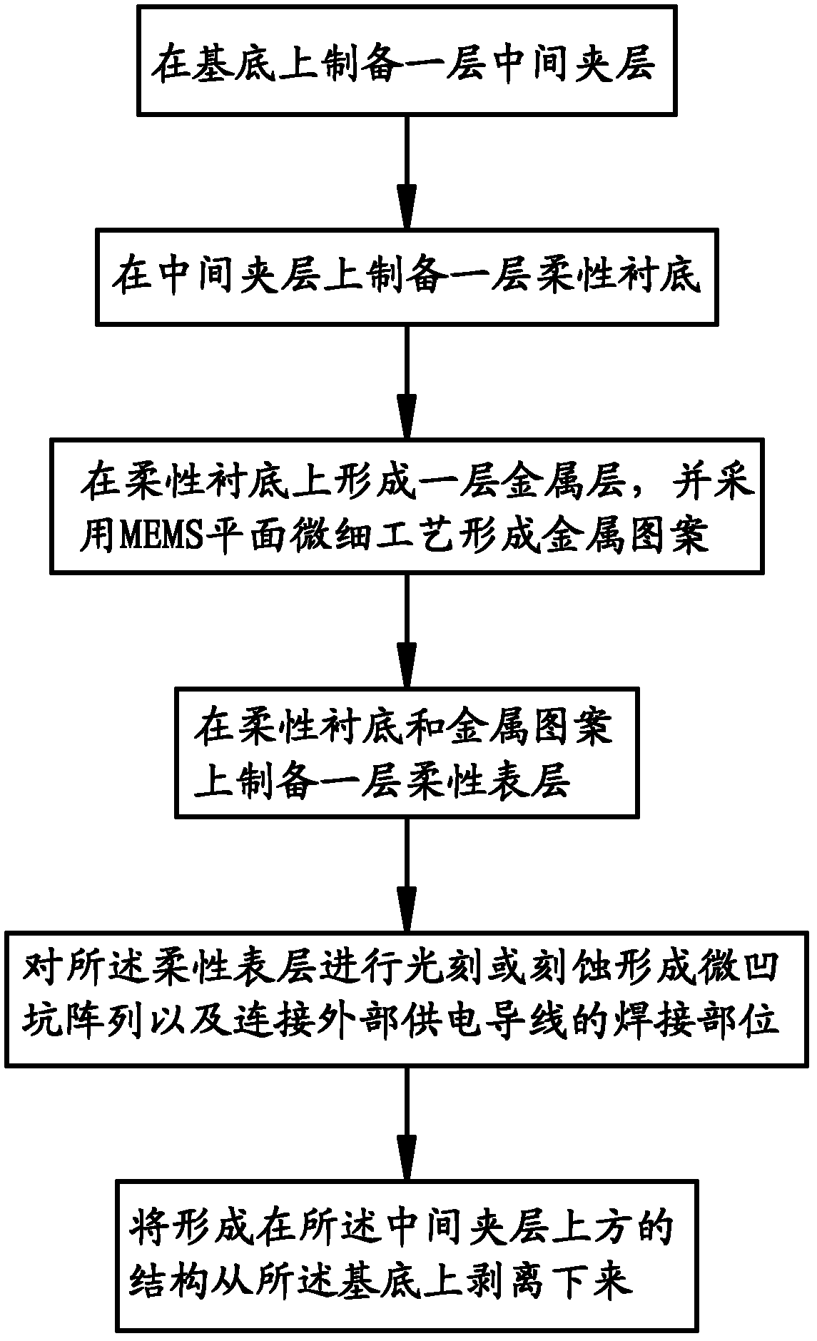
[0046] The manufacturing method comprises the steps of:

[0047] 1.1. Prepare the hard substrate: select ordinary single-polished silicon wafers as the carrier for the entire flexible drag-reducing skin processing.

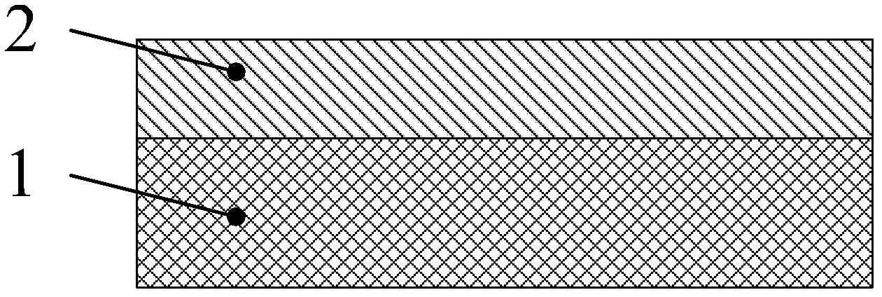
[0048]1.2. Preparation of intermediate interlayer: mix PDMS monomer and curing agent at a ratio of 5:1 to 20:1 by mass of the monomer, stir well and vacuumize for 15 minutes to remove air bubbles in the mixture. Spin-coat the uniformly mixed solution on a hard substrate using a homogenizer, then place it in an oven, and heat it at 90°C for 60 minutes to cure the PDMS. In this step, PDMS films with different thicknesses can be obtained by adjusting the rotation speed of the glue leveling machine and selecting different glue leveling-curing times. The thickness of the PDMS film in this embodiment is 20 μm.

[0049] 1.3. Preparation of flexible substrate: Spin-coat polyimide prepolymer coating glue on the intermediate interlayer, and heat and cure. In this step, p...

Embodiment 2

[0055] The manufacturing method comprises the steps of:

[0056] 2.1. Prepare the hard substrate: choose a polished metal sheet as the carrier for the entire flexible drag-reducing skin processing.

[0057] 2.2. Preparation of the interlayer: mix the PDMS monomer and the curing agent at a mass ratio of 5:1 to 20:1, stir well and vacuumize for 15 minutes to remove air bubbles in the mixture. Spin-coat the uniformly mixed solution on a hard substrate using a homogenizer, then place it in an oven, and heat it at 90°C for 60 minutes to cure the PDMS. In this step, PDMS films with different thicknesses can be obtained by adjusting the rotation speed of the glue leveling machine and selecting different glue leveling-curing times. The thickness of the PDMS film in this embodiment is 200 μm.

[0058] 2.3. Preparation of flexible substrate: Spin-coat polyimide prepolymer coating adhesive on the intermediate interlayer, and heat and cure. In this step, polyimide films with different ...


PUM

PropertyMeasurementUnit
thicknessaaaaaaaaaa
thicknessaaaaaaaaaa
thicknessaaaaaaaaaa

Abstract

The invention discloses a method for manufacturing a flexible micro electro mechanical system (MEMS) resistance reducing covering, and mainly aims to provide an improved manufacturing process. The method for manufacturing the resistance reducing covering comprises the following steps of: 1, preparing a middle interlayer on a substrate; 2, preparing a flexible underlayer on the substrate subjected to the step 1; 3, forming a metal layer on the substrate subjected to the step 2, and forming an electrolytic anode, an electrolytic cathode, an anode lead terminal, a cathode lead terminal and an internal connection by adopting an MEMS plane micro process; 4, preparing a flexible surface layer on the substrate subjected to the step 3, and forming a micro-pit array and a welding position connected with an external electric power conductor through photoetching or etching; and 5, peeling the structure formed on the middle interlayer from the substrate. A positive sequence method is adopted, namely the flexible underlayer is prepared first and then the flexible surface layer is prepared, procedures are reduced and the manufacturing process is simplified.

Description

technical field [0001] The invention relates to the technical fields of micro-manufacturing and flexible MEMS, in particular to a method for manufacturing a flexible MEMS (Micro Electro-Mechanical Systems) drag-reducing skin. Background technique [0002] The travel resistance encountered by water surface and underwater vehicles includes pressure difference resistance, traveling wave resistance and surface friction resistance, among which surface friction usually occupies the largest proportion. For vehicles with large length and aspect ratio / length-to-diameter ratio This is especially true. Therefore, reducing the frictional resistance of the surface of the vehicle can effectively increase the speed, increase the range, and reduce energy consumption, which has great economic value. [0003] At present, the theoretical and applied research of frictional drag reduction technology mainly focuses on the turbulent boundary layer, involving a variety of technical solutions, such...

Claims


Application Information

Patent Timeline
Patent Type & Authority Patents(China)
IPC IPC(8): B81C1/00
Inventor 李勇李文平朱效谷
Owner TSINGHUA UNIV
Learn More