Gas purifying method and gas purifying apparatus

A technology for gas purification and raw gas, applied in chemical instruments and methods, inert gas compounds, separation methods, etc., can solve the problems of high manufacturing costs and expensive adsorbents, and achieve a reduction in filling amount, filling amount, and manufacturing. cost effect

Inactive Publication Date: 2012-03-21
NIPPON SANSO CORP
View PDF10 Cites 21 Cited by
  • Summary
  • Abstract
  • Description
  • Claims
  • Application Information

AI Technical Summary

Problems solved by technology

In addition, the manufacturing cost becomes high due to the expensive adsorbent

Method used


Image

  • Gas purifying method and gas purifying apparatus
  • Gas purifying method and gas purifying apparatus
  • Gas purifying method and gas purifying apparatus

Examples


Embodiment 1

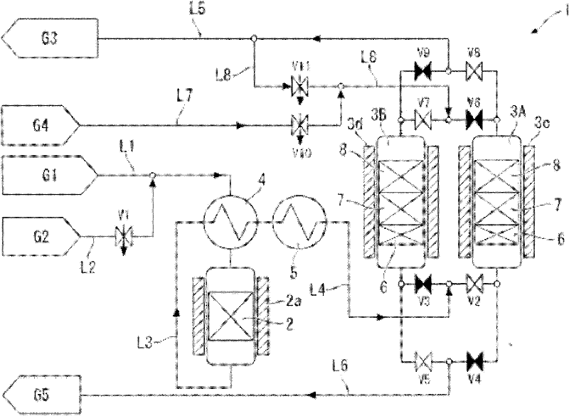
[0096] A stainless steel cylinder with an inner diameter of 100 mm was filled with a 400 mm alumina-supported Pd catalyst as the catalyst tower 2 . A moisture adsorbent layer 6 (MS5A) consisting of a zeolite layer with a thickness of 100 mm, a nickel catalyst layer 7 (N112) with a thickness of 50 mm, and a 250 mm-thick The alumina layer 8 containing sodium in a weight ratio of 5.8% was used as the adsorption tower 3A.

[0097] First, each layer of the adsorption tower 3A was regenerated under the following conditions.

[0098] First, make nitrogen containing hydrogen concentration 2vol% pass through passage L7 and passage L8 at 2Nm 3 The flow rate per hour was introduced into the adsorption tower 3A for 3 hours, and heated to 200°C by the heater 3c. Next, in nitrogen at 2Nm 3 After the flow rate per hour flows into the adsorption tower 3A, the adsorption tower 3A is cooled.

[0099] Next, an adsorption step is performed.

[0100] Nitrogen containing 1ppm of methane, 1ppm ...

Embodiment 2

[0103] A stainless steel cylinder with an inner diameter of 100 mm was filled with a 400 mm alumina-supported Pt catalyst as the catalyst tower 2 . A moisture adsorbent layer 6 (MS5A) consisting of a zeolite layer with a thickness of 100 mm, a nickel catalyst layer 7 (N112) with a thickness of 50 mm, and a thickness of A 250mm alumina layer 8 containing sodium in a weight ratio of 5.8% was used as the adsorption tower 3A.

[0104] Next, after regenerating the adsorption tower 3A under the same conditions as in Example 1, an adsorption step was performed under the same conditions as in Example 1.

[0105] Oxygen was detected as the first breakthrough component 49 hours after the start of introduction of the raw material gas into the catalyst tower 2 and the adsorption tower 3A.

Embodiment 3

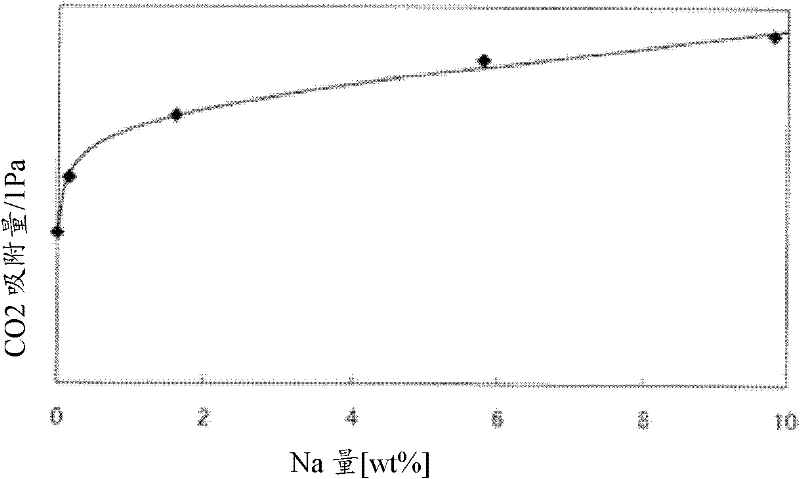
[0124] Under the condition that the partial pressure of carbon dioxide is 1 Pa, the carbon dioxide adsorption capacity of alumina is determined by changing the sodium content. As a result, compared with the carbon dioxide adsorption capacity of alumina with a sodium content of 0.1wt%, 1.6wt%, 5.8wt%, and 9.8wt%, which were 38, 50, 60, and 65 mmol / kg, respectively, alumina with a sodium content of 0.1wt% or less The carbon dioxide adsorption capacity is 28mmol / kg. The results are shown in the graph where the horizontal axis is the sodium content and the vertical axis is the carbon dioxide adsorption amount. image 3 middle. image 3 The carbon dioxide adsorption amount shown was measured using a constant volume type gas adsorption amount measuring device (Baratron electrostatic volumetric manometer (manufactured by MKS Co., Ltd.) with a full scale of 13.2 Pa) at a set temperature of 25° C. and a pressure of 1Pa to carry out.

[0125] Depend on image 3 It can be seen from t...


PUM


Abstract

The present invention provides a gas purifying method, characterized by comprising the steps of contacting a raw material gap with a catalyst to form carbon dioxide and water; contacting the raw material gas after contacting with the catalyst with a water adsorbent for removing the water; contacting the raw material gas with the water removed with a nickel catalyst for removing reaction residuum oxygen; and contacting the raw material gas with the oxygen removed with an aluminum oxide containing 0.1-10 wt% sodium for removing the carbon dioxide. According to the present invention, the gas purifying method and the gas purifying apparatus can remove hydrocarbon, hydrogen, carbon monoxide, carbon dioxide, oxygen and water contained in the raw material gas containing nitrogen or rare gas, thereby enabling the purifying apparatus to be miniaturized, reducing the filling amount of the costly nickel catalyst, and reducing the purification cost.

Description

technical field [0001] The present invention relates to a method and an apparatus for purifying hydrocarbons, hydrogen, carbon monoxide, carbon dioxide, oxygen, and water contained in inert gases such as nitrogen and argon used in semiconductor manufacturing and the like. Background technique [0002] High-purity inert gases such as nitrogen and argon are required in the semiconductor manufacturing process. These inert gases are usually produced by cryogenic air separation units. The inert gas produced by the cryogenic air separation unit contains methane, hydrogen, carbon monoxide, carbon dioxide, oxygen, and water at the ppm to ppb level as impurities. [0003] In recent years, with the high integration of semiconductors, the impurity concentration in the inert gas used in the semiconductor manufacturing process is expected to be ppb or less. Therefore, it is necessary to further purify the source gas of the inert gas, but it is difficult to effectively remove the hydroc...

Claims


Application Information

Patent Timeline
Patent Type & Authority Applications(China)
IPC IPC(8): B01D53/86B01D53/04B01D53/62B01D53/72C01B23/00C01B21/04
CPCY02A50/20Y02C20/40Y02P20/151B01D53/02B01D53/26B01D53/86
Inventor 足立贵义藤江和彦
Owner NIPPON SANSO CORP
Why Eureka
Try Eureka