Eureka AIR delivers breakthrough ideas for toughest innovation challenges, trusted by R&D personnel around the world.

Metal back electrode of flexible film solar cell and preparation method thereof

A metal back electrode and solar cell technology, which is applied in the field of solar cells, can solve the problems of no patent disclosure of light trapping effect, and achieve the effects of improving sunlight utilization, shortening production cycle, and improving cell efficiency

Inactive Publication Date: 2012-04-04
BAODING TIANWEI GRP CO LTD
View PDF10 Cites 8 Cited by
  • Summary
  • Abstract
  • Description
  • Claims
  • Application Information

AI Technical Summary

Problems solved by technology

Most of the published patents focus on the structure and preparation of flexible solar cells. There is no patent disclosure on the light trapping effect, and there is no report on the realization of the back light trapping effect by improving the preparation method of the back electrode in the published research work.

Method used


Image

  • Metal back electrode of flexible film solar cell and preparation method thereof
  • Metal back electrode of flexible film solar cell and preparation method thereof
  • Metal back electrode of flexible film solar cell and preparation method thereof

Examples


Embodiment 1

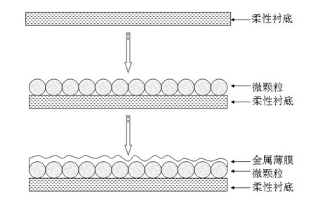
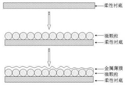
[0019] First, use the polyimide film after ultrasonic cleaning as the flexible substrate, and use the spin coating method to coat a layer of TiO on the polyimide film 2 Particles, TiO 2 The diameter of the particles is between 10 nm and 1 μm. Then, a magnetron sputtering method is used to directly grow an aluminum thin film on the polyimide film coated with microparticles.

[0020] In the above deposition process, the gas pressure is 3-30 mTorr, the radio frequency power is 100-250 W, the argon flow rate is 2-20 sccm, and the deposition temperature is room temperature. The thickness of the aluminum film can be changed by adjusting the deposition time.

[0021] After magnetron sputtering the aluminum film, a metal film with a textured structure can be obtained, which can be used as a back electrode to prepare a thin-film silicon flexible battery.

Embodiment 2

[0023] As in the method for preparing the aluminum film described in Example 1, the aluminum film is prepared by the evaporation method, and the obtained aluminum film also has a texture structure.

Embodiment 3

[0025] First, a sputtering method is used to prepare a ZnO film on a polyimide substrate. The deposition process is: gas pressure 3-30mTorr, radio frequency power 100-250W, argon flow rate 2-20sccm, and deposition temperature at room temperature-200°C. Then, the ZnO thin film is etched by wet chemical method to obtain a suede structure. The concentration of the etching solution used is 0.1-5wt%, and it can be an acidic or alkaline solution. Finally, the aluminum film preparation method described in Examples 1 and 2 is used to obtain a textured aluminum film back electrode.


PUM

PropertyMeasurementUnit
diameteraaaaaaaaaa
diameteraaaaaaaaaa

Abstract

The invention relates to a metal back electrode of flexible film solar cell and a preparation method thereof, which belong to the technical field of solar cell. The technical solution is that a metal back electrode with texture structure on the surface is directly prepared on a flexible substrate, and the method comprises the following technological steps of: (1) forming a concave-convex texture structure on the flexible substrate; and (2) depositing a metal film on a substrate with the concave-convex surface structure as the metal back electrode of the flexible cell. The method for preparing the flexible film solar cell by using the texture metal back electrode has the following advantages that: 1) the surface structure of the back electrode can be adjusted by changing microparticle size and interval, which is convenient, flexible and favorable for realizing optimization of technological parameters; 2) the metal back electrode has high reflection rate, and can improve utilization rate of sunlight and improve efficiency of the solar cell; and 3) the sunlight has high optical distance in the cell, so thickness of absorption layer of film battery can be reduced, production time can be shortened, production cost can be reduced and production efficiency is improved.

Description

technical field [0001] The invention relates to a metal back electrode of a flexible thin-film solar cell and a preparation method thereof, belonging to the technical field of solar cells. Background technique [0002] Compared with the first-generation crystalline silicon solar cells, thin-film solar cells have the advantages of low production cost and saving raw materials. With the continuous improvement of cell efficiency in recent years, thin-film solar cells have shown great development potential, and have become a research hotspot in the field of solar cells in recent years. Thin-film solar cells can be divided into two categories: hard substrate solar cells (such as glass substrates) and flexible solar cells (such as polyimide or stainless steel substrates) according to different substrate properties. Compared with glass substrates, flexible substrates have the advantages of light weight, foldability, and unbreakability. The prepared flexible solar cells have a high ...

Claims


Application Information

Patent Timeline
Patent Type & Authority Applications(China)
IPC IPC(8): H01L31/18H01L31/0224H01L31/052H01L31/056
CPCY02E10/52Y02P70/50
Inventor 潘清涛宋鑫胡增鑫贾海军麦耀华
Owner BAODING TIANWEI GRP CO LTD
Why Eureka
Eureka Blog
Learn More