
Sieve-plate tower used for sintering machine flue gas desulfurization and desulfurization process thereof

The technology of a sintering machine and a sieve tray tower is applied in the separation of dispersed particles, chemical instruments and methods, separation methods, etc., and can solve the problems of difficulty in controlling the pH value of the system slurry, increasing the resistance of the sieve tray layer, and wasting system energy consumption, etc. Achieve the effect of reducing investment and operating costs, increasing desulfurization capacity and desulfurization efficiency, and improving absorption efficiency

Inactive Publication Date: 2012-06-27
ZHEJIANG TIANLAN ENVIRONMENTAL PROTECTION TECH
View PDF5 Cites 13 Cited by
  • Summary
  • Abstract
  • Description
  • Claims
  • Application Information

AI Technical Summary

Problems solved by technology

This invention improves the desulfurization efficiency, but also has the following disadvantages: ①The limestone slurry tank is connected with the absorption tower, there is no slurry pool in the absorption tower, the absorption zone is separated from the oxidation zone, and it is difficult to control the pH value of the system slurry
② There is no control over the aperture, resistance and residence time of the sieve plate. When no overflow weir is installed, the thickness of the liquid layer on each sieve plate will be too large, which will increase the resistance of the sieve plate layer to the flue gas and waste the system. energy consumption

Method used


Image

  • Sieve-plate tower used for sintering machine flue gas desulfurization and desulfurization process thereof
  • Sieve-plate tower used for sintering machine flue gas desulfurization and desulfurization process thereof
  • Sieve-plate tower used for sintering machine flue gas desulfurization and desulfurization process thereof

Examples


Embodiment 1

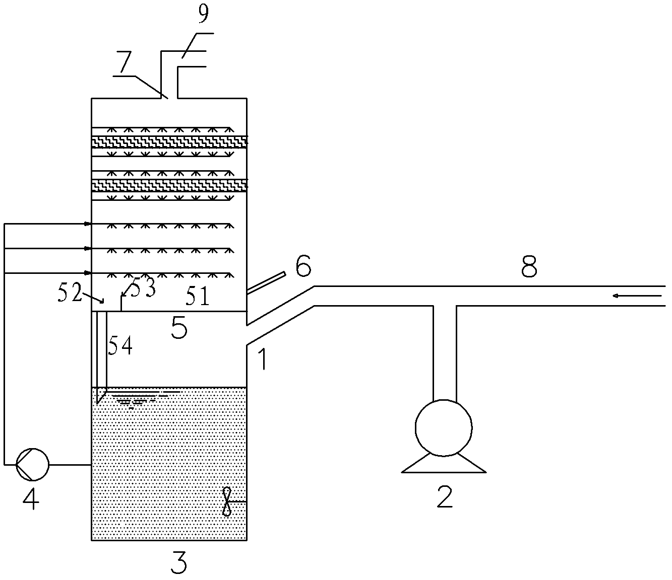
[0032] A steel group 1×200m 2 The flue gas desulfurization project of the sintering machine adopts the sieve plate tower and its desulfurization process of the present invention for flue gas desulfurization, and the desulfurizing agent is limestone. The liquid-gas ratio of wet desulfurization is 6L / m 3 , the pH control is 5.4, the residence time of the slurry in the gas-liquid contact area is 100s (that is, the height of the overflow weir is 33cm), the thickness of the sieve plate is 2cm, the opening rate is 45%, and the pore diameter is 6cm. The area ratio of the flow area is 7:3, the diameter of the overflow pipe is 70cm, the length is 400cm, and the inlet SO 2 The concentration is 2360mg / Nm 3 , SO after desulfurization 2 The concentration is 86mg / Nm 3 , the purity of the gypsum is 92.8%, and the residual amount of desulfurizer in the gypsum is less than 0.2%.

Embodiment 2

[0034] A steel group 2×160m 2 The flue gas desulfurization project of the sintering machine adopts the sieve plate tower and its desulfurization process of the present invention for flue gas desulfurization, and the desulfurizing agent is lime. The wet desulfurization liquid-gas ratio is 5L / m 3 , the pH control is 5.2, the residence time of the slurry in the gas-liquid contact area is 130s (that is, the height of the overflow weir is 35cm), the thickness of the sieve plate is 2cm, the opening rate is 48%, and the pore diameter is 7cm. The area ratio of the flow area is 13:5, the diameter of the overflow pipe is 60cm, the length is 380cm, and the inlet SO 2 The concentration is 1830mg / Nm 3 , SO after desulfurization 2 The concentration is 65mg / Nm 3 , the purity of the gypsum is 93.1%, and the residual amount of desulfurizer in the gypsum is less than 0.2%.

Embodiment 3

[0036] A steel group 1×180m 2 The flue gas desulfurization project of the sintering machine adopts the sieve plate tower and its desulfurization process of the present invention for flue gas desulfurization, and the desulfurizing agent is limestone. The liquid-gas ratio of wet desulfurization is 7L / m 3 , the pH control is 5.4, the residence time of the slurry in the gas-liquid contact area is 90s (that is, the height of the overflow weir is 32cm), the thickness of the sieve plate is 2cm, the opening rate is 50%, and the pore diameter is 6cm. The area ratio of the flow area is 7:3, the diameter of the overflow pipe is 65cm, the length is 370cm, and the inlet SO 2 The concentration is 2010mg / Nm 3 . SO after desulfurization 2 The concentration is 71mg / Nm 3 , the purity of the gypsum is 91.6%, and the residual amount of desulfurizer in the gypsum is less than 0.2%.


PUM


Abstract

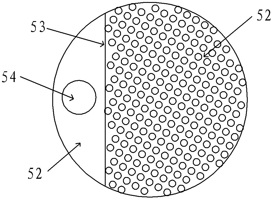
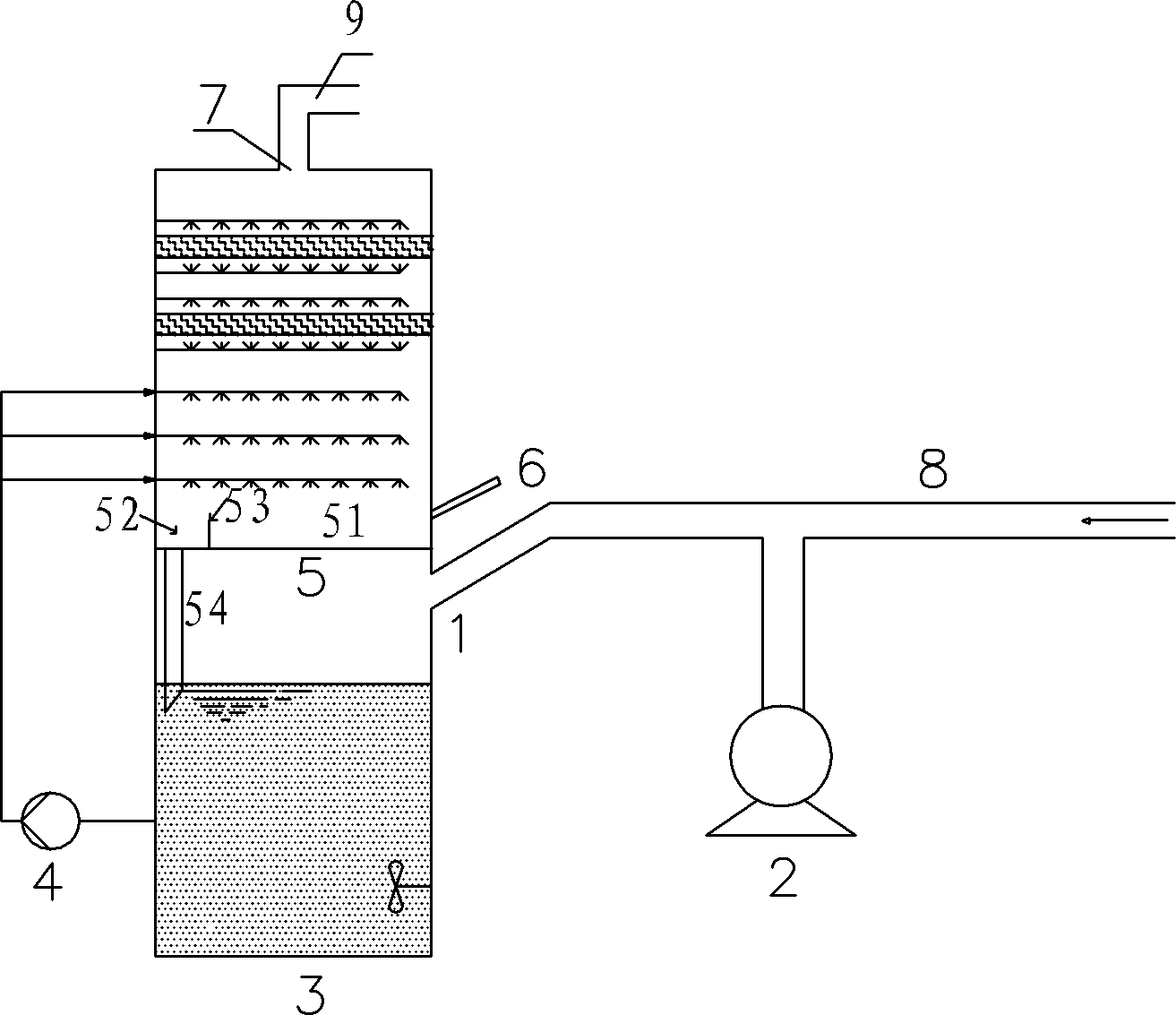
The invention discloses a sieve-plate tower used for sintering machine flue gas desulfurization and a desulfurization process thereof, and belongs to the field of resource and environment protection. The device comprises an absorption tower, wherein the absorption tower is provided with a flue gas inlet, a flue gas outlet and a desulfurizer inlet, a demisting layer, a spraying layer, a sieve plate and a pulp chest are sequentially arranged in the absorption tower from top to bottom, the desulfurizer inlet is positioned above the flue gas inlet, the sieve plate is positioned between the desulfurizer inlet and the flue gas inlet, an overflow weir is arranged above the sieve plate, the sieve plate is divided into an overflow area and a gas liquid contact area by the overflow weir, sieve pores of the sieve plate are arranged in the gas liquid contact area, the gas liquid contact area is positioned at one side of the sieve plate close to the desulfurizer inlet, and an overflow pipe is arranged under the overflow area. The desulfurization process comprises the following steps that: sintering machine flue gas enters the absorption tower to be reacted with the desulfurizer at the gas liquid contact area and then is discharged after sulfur dioxide is removed, and desulfurized pulp generated by the reaction of the flue gas and the desulfurizer overflows into the pulp chest of the absorption tower. The invention is used for removing the sulfur dioxide in the sintering machine flue gas, the flue gas desulfurization efficiency is improved, and the desulphurization energy consumption is reduced.

Description

technical field [0001] The invention relates to the field of resources and environmental protection, in particular to a sieve plate tower used for desulfurization of flue gas of a sintering machine and a desulfurization process thereof. Background technique [0002] The flue gas of the sintering machine is the dusty exhaust gas generated during the high-temperature sintering process after the sintering mixture is ignited and runs with the trolley. The sintering process is carried out in a completely open and oxygen-enriched environment. The waste gas system is discharged after dedusting, and the flue gas of the sintering machine has the characteristics of large flue gas volume, high oxygen content, SO 2 The emission concentration is low, the fluctuation range is large, the dust content is high, and it contains a variety of corrosive gases and heavy metal pollutants. Each ton of sinter can produce about 4000~6000m 3 The flue gas, the oxygen content of the sintering machine ...

Claims


Application Information

Patent Timeline
Patent Type & Authority Applications(China)
IPC IPC(8): B01D53/80B01D53/50
Inventor 李泽清莫建松程常杰吴忠标
Owner ZHEJIANG TIANLAN ENVIRONMENTAL PROTECTION TECH
Learn More