Oxidation reduction furnace and method for treating waste remained after dust-removal of iron and steel enterprises

A reduction furnace and waste technology, applied in waste heat treatment, furnaces, vertical furnaces, etc., can solve the problems of increased energy consumption, large heat loss, circulation pollution, etc., to avoid damage and agglomeration, reduce collision and friction, restore full effect

Active Publication Date: 2012-08-08
袁志君
View PDF5 Cites 1 Cited by
  • Summary
  • Abstract
  • Description
  • Claims
  • Application Information

AI Technical Summary

Problems solved by technology

[0004] 1. The oxide produced by the rotary kiln belongs to the oxidizing atmosphere, the cooling system is too long, the heat loss is too large, and the energy consumption is high. The content of zinc in the remaining slag is 2%-4%, and the content of fixed carbon is 25%-30%. The content of iron is nearly 30%, and there are defects of agglomeration and furnace blockage, and the raw materials used have great limitations
[0005] 2. The oxide produced by the open hearth furnace belongs to the oxidizing atmosphere, the cooling system is too long, the heat loss is too large, and the energy consumption is high. The oxide content in the remaining slag is 2%-4%, the fixed carbon content is about 10%, and the ferrous content Nearly 50%, basically can not be reused, are discarded
[0006] 3. Some methods for extracting alkali metals can extract a part of alkali metals, but this method has a long process and high energy consumption. The extracted solids also contain alkali metals, and the metal oxides are not extracted at all, so returning to sintering also causes Pollution, increased energy consumption, is an endless cycle of pollution

Method used


Image

  • Oxidation reduction furnace and method for treating waste remained after dust-removal of iron and steel enterprises
  • Oxidation reduction furnace and method for treating waste remained after dust-removal of iron and steel enterprises
  • Oxidation reduction furnace and method for treating waste remained after dust-removal of iron and steel enterprises

Examples


Embodiment 1

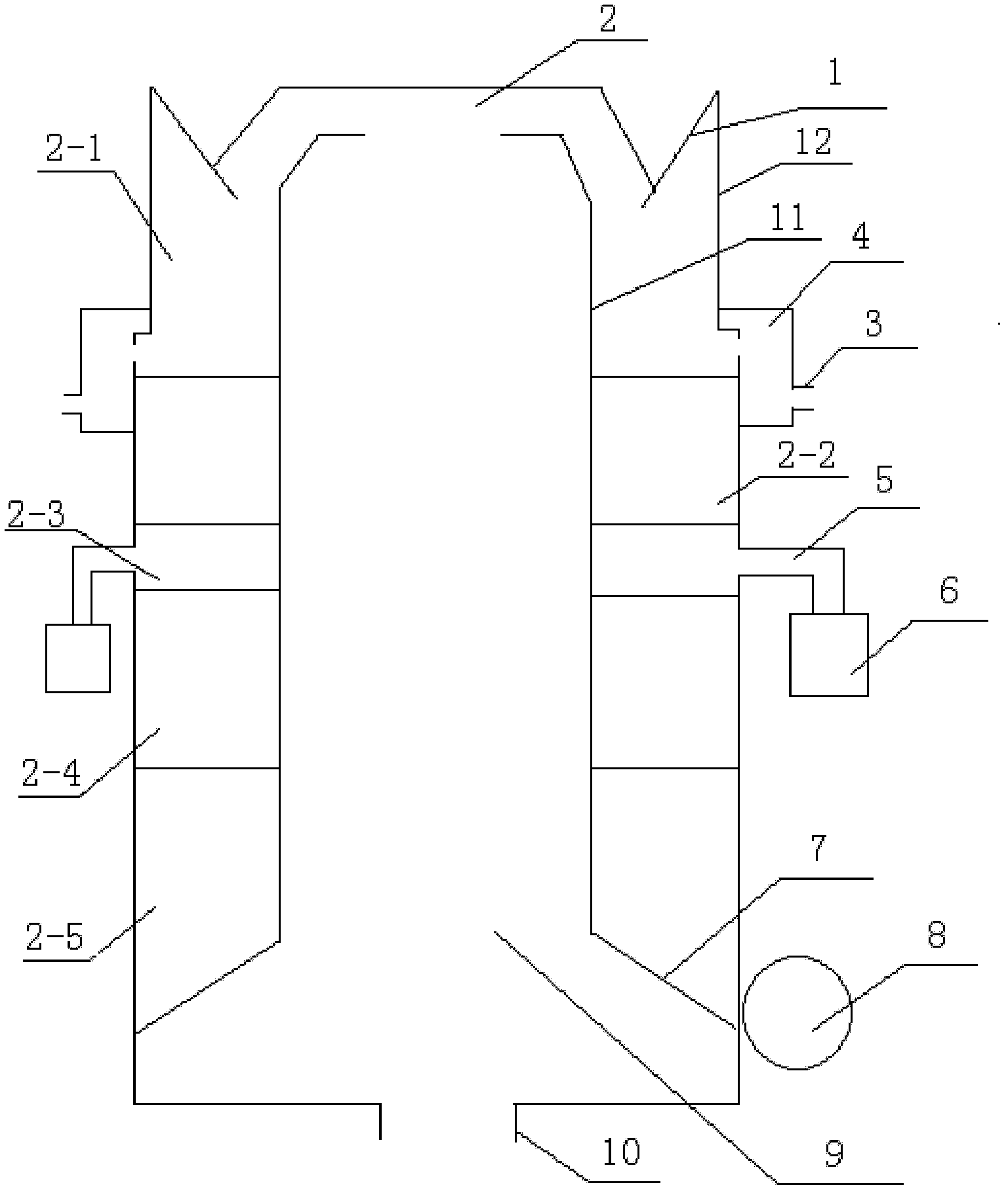
[0030] Embodiment 1: a kind of redox furnace (see Figure 1-2 ), characterized in that it consists of a hopper 1, furnace inner wall 11, furnace outer wall 12, flue 9, furnace cavity 2, combustion chamber 4, gas nozzle 3, gas channel 5, gas electromagnetic heater 6, lower hopper 7, lower The feeder 8 and the gas outlet 10 are formed; the hopper 1 is located at the top of the redox furnace; the flue 9 is the space within the furnace inner wall 11; the furnace cavity 2 is the furnace inner wall 11 and the furnace outer wall 12 The overall space between them is divided into preheating oxidation zone 2-1, reduction zone 2-2, gas zone 2-3, cooling zone 2-4 and discharge zone 2-5 from top to bottom according to the working temperature ; Said combustion chamber 4 is located at the side of the oxidation-reduction furnace, and is fixedly connected with the outer wall 12 of the furnace; said gas nozzle 3 is fixed on the combustion chamber 4; The gas belt 2-3 in 2 is connected; said low...

Embodiment 2

[0047] Embodiment 2: A redox furnace, characterized in that it consists of a hopper 1, furnace inner wall 11, furnace outer wall 12, flue 9, furnace cavity 2, combustion chamber 4, gas nozzle 3, gas channel 5, gas electromagnetic heating device 6, hopper 7, feeder 8 and gas outlet 10; said hopper 1 is located at the top of the redox furnace; said flue 9 is the space within the inner wall 11 of the furnace; said furnace chamber 2 It is the overall space between the furnace inner wall 11 and the furnace outer wall 12. According to the temperature difference during operation, it is divided into preheating oxidation zone 2-1, reduction zone 2-2, gas zone 2-3, and cooling zone 2-2 from top to bottom. 4 and discharge interval 2-5; said combustion chamber 4 is located at the side of the redox furnace, and is fixedly connected with the furnace outer wall 12; said gas nozzle 3 is fixed on combustion chamber 4; said gas electromagnetic heater 6 communicates with the gas belt 2-3 in the ...

Embodiment 3

[0065] A redox furnace, characterized in that it consists of a hopper 1, a furnace inner wall 11, a furnace outer wall 12, a flue 9, a furnace chamber 2, a combustion chamber 4, a gas nozzle 3, a gas channel 5, a gas electromagnetic heater 6, a lower The hopper 7, the feeder 8 and the gas outlet 10 are composed; the hopper 1 is located at the top of the redox furnace; the flue 9 is the space inside the inner wall 11 of the furnace; the furnace chamber 2 is the inner wall 11 of the furnace. The overall space between the furnace outer wall 12 is divided into preheating oxidation zone 2-1, reduction zone 2-2, gas belt 2-3, cooling zone 2-4 and discharge zone from top to bottom according to the temperature difference during operation. Interval 2-5; said combustion chamber 4 is located at the side of the oxidation-reduction furnace, and is fixedly connected with the outer wall 12 of the furnace; said gas nozzle 3 is fixed on the combustion chamber 4; said gas electromagnetic heater ...


PUM


Abstract

The invention discloses an oxidation reduction furnace and a method for treating waste remained after dust-removal of iron and steel enterprises. The oxidation reduction furnace comprises a feeding hopper, an inner wall, an outer wall, a flue, a furnace chamber, a burning chamber, a gas nozzle, a gas passage, a gas electromagnetic heater, a discharging hopper, a discharging device and a gas outlet. The method for treating the waste remained after dust-removal of the iron and steel enterprises is characterized that the waste remained after dust-removal is pelletized and placed into the oxidation reduction furnace and heated to 1100 to 1250 DEG C, and the gas is introduced into the oxidation reduction furnace so as to complete the reduction and the oxidation in one step. The invention has advantages that: 1, the oxidation-reduction reaction is completed in one furnace; 2, the waste is in contact with the gas at the high temperature, so that the differentiation problem at a low temperature can be solved; 3, the gas electromagnetic heater is used for heating the gas to a given temperature, so that the temperature balance inside the furnace can be ensured; 4, the discharging device is utilized to ensure uniform discharging; and 5, the height of the burning chamber is increased, and the temperature of a reduction interval is increased, so that the reduction is carried out more adequately.

Description

(1) Technical field: [0001] The invention relates to the field of metallurgical equipment, in particular to an oxidation process for producing iron fine powder, zinc oxide, lead oxide, silver oxide and other non-ferrous metal oxides and potassium chloride, magnesium chloride, and sodium chloride by utilizing the dust removal waste resources of iron and steel enterprises. Reduction furnace and method of operation thereof. (two) background technology: [0002] The dust removal waste of iron and steel enterprises has the characteristics of low grade and high oxides, so the general kiln cannot solve the problems of low ball strength, agglomeration in the sintering process, and low-temperature pulverization in the production process. Enterprises, small businesses can't use the fraudulent use of the situation, all directly into the sintering recovery of a small amount of iron, which will not only cause long-term and repeated pollution to the environment but also waste resources an...

Claims


Application Information

Patent Timeline
IPC IPC(8): F27B1/04F27B1/12F27B1/21F27D17/00C22B7/00
CPCY02P10/20
Inventor 袁子金
Owner 袁志君
Why Eureka
Try Eureka