
Method and device for realizing liquid crystal arbitrary orientation control through numerical control micromirror array photoetching

A digitally controlled micromirror and orientation control technology, which is applied in microlithography exposure equipment, photolithography exposure devices, optics, etc., can solve the problem of inability to achieve arbitrary polarization state control in different orientation regions, difficulty in preparing complex patterns, and graphic resolution. Limitation and other issues, to achieve the effect of enriching the tuning control dimension, improving the tuning control dimension, and saving production costs

Inactive Publication Date: 2012-11-07
NANJING UNIV
View PDF6 Cites 27 Cited by
  • Summary
  • Abstract
  • Description
  • Claims
  • Application Information

AI Technical Summary

Problems solved by technology

Projection lithography is a micro-machining technology that replicates a mask pattern. It requires a specific mask. The conversion of the pattern must be achieved by replacing the mask. Replacing the mask will involve a series of mechanical alignment, so the process cost is high and the efficiency is high. lower
Due to the broadening phenomenon of the beam after passing through the substrate, the pattern resolution is limited; and it is not possible to achieve arbitrary polarization state control in different orientation regions
The other is to use the holographic interference method to obtain periodic liquid crystal alignment, which has the disadvantage that it is difficult to prepare complex patterns

Method used


Image

  • Method and device for realizing liquid crystal arbitrary orientation control through numerical control micromirror array photoetching
  • Method and device for realizing liquid crystal arbitrary orientation control through numerical control micromirror array photoetching
  • Method and device for realizing liquid crystal arbitrary orientation control through numerical control micromirror array photoetching

Examples


Embodiment 2

[0040] A DMD-based lithography system was used to realize the fabrication of polarization controller arrays.

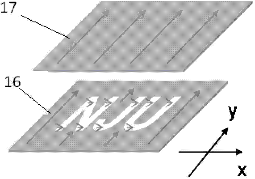
[0041] A DMD photolithography system and steps similar to those in Example 1 were used, a 1000W ultraviolet light source was used, and a cinnamate-based photoalignment agent was used. When exposing the substrate 2, such as Figure 5 As shown, let the DMD output the word "NJU" first, and adjust the direction of the polarizer so that the orientation direction of the exposure area is perpendicular to the orientation direction of the substrate 1 . Then change the output graphics of DMD, exposure in turn Figure 5 For each circular area in , different polarizer orientations are selected for each exposure. After the exposure, according to the step (4) of Example 1, two substrates were formed into a liquid crystal cell. In this way, in different regions of the liquid crystal cell, the liquid crystal molecules will have different twist angles. Here, the letter "NJU" and t...

Embodiment 3

[0043] The phase retarder array was fabricated using a DMD-based photolithography system.

[0044] A DMD photolithography system and steps similar to those in Examples 1 and 2 were used, a 1000W ultraviolet light source was used, and a polyimide-based photoalignment agent was used. Firstly, two substrates oriented in the same direction are made into a liquid crystal cell. Then use the DMD photolithography system to expose step by step. First, let the DMD output the word "NJU" in the pattern, and adjust the direction of the polarizer so that the orientation direction of the exposure area is perpendicular to the orientation direction of the two substrates. Then change the output graphics of DMD, exposure in turn Figure 6 Each numbered field in each exposure rotates a different polarizer orientation. As shown by the numbers in the figure, the included angles between the liquid crystal orientation and the preset orientation are 90°, 80°, 70°, 60°...10° in sequence. After the e...


PUM

PropertyMeasurementUnit
widthaaaaaaaaaa

Abstract

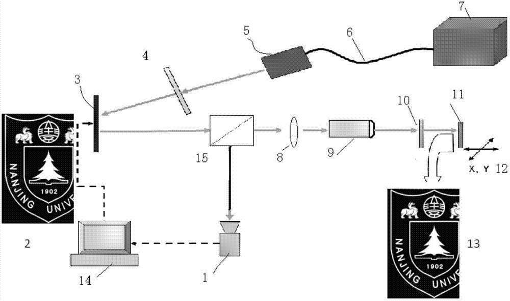
A method for realizing liquid crystal arbitrary orientation control through numerical control micromirror array photoetching utilizes a set of projection photoetching system based on a digital micromirror device (DMD), so the collimated ultraviolet or blue light beams are uniformly irradiated to the surface of the numerical control micromirror array DMD, a computer outputs a shape signal to control all the DMD pixels, i.e. single micromirrors are in different reflection states for realizing intermediate photomask, so the all the DMD pixel reflected lights carry out the shape signal control; the beams are demagnified by a microobjective, and then are projected onto a substrate which has the surface coated with a light-operated orientation material through a polarizing film, exposure is completed through controlling the light intensity and time, and the liquid crystal of an exposure pattern area is reorientated; and another substrate is utilized to form a liquid crystal cell, the liquid crystal cell is filled with the liquid crystal, so preset orientation is realized. The method realizes the control and production of arbitrary patterns and orientation directions, and has a potential important application in the fields of wide viewing angle liquid crystal display, adjustable optical communication devices, wavefront correction, light beam control and the like.

Description

technical field [0001] The invention belongs to a method for realizing the orientation control of a liquid crystal selection area. Specifically, the digital control micro-mirror array DMD is used as a dynamic mask to selectively control the reflection state of different areas of the beam, to realize maskless exposure of the photo-controlled alignment material, and then to realize the orientation control of the selected area of ​​the liquid crystal. It involves several technical fields such as microlithography system, liquid crystal orientation control, and preparation of electro-optical adjustable components. Background technique [0002] Liquid crystals are widely used in information display, optical and photonic devices and other fields. High-quality liquid crystal orientation control is a prerequisite for all applications of nematic liquid crystals. Rubbing orientation is the most widely used technology in the industry, but the traditional rubbing orientation method is ...

Claims


Application Information

Patent Timeline
Patent Type & Authority Applications(China)
IPC IPC(8): G03F7/20G02F1/1337
Inventor 陆延青吴皓胡伟林晓雯徐飞
Owner NANJING UNIV
Learn More