Low-concentration flue gas infra-red analyzer and detection method

An infrared analyzer, low-concentration technology, applied in the analysis of materials, material analysis through optical means, instruments, etc., can solve the problem of easy-to-interference discharge detector measurement accuracy, high mirror structure and process requirements, and difficult low-concentration Gas measurement and other issues to achieve the effect of ensuring detection accuracy and sensitivity, improving flatness, and reducing drift

Active Publication Date: 2012-12-05
NANJING ASSEN ENVIRONMENT TECH
View PDF8 Cites 18 Cited by
  • Summary
  • Abstract
  • Description
  • Claims
  • Application Information

AI Technical Summary

Problems solved by technology

[0005] 1) For the sample cell or absorption cell, if a multi-reflection cell structure is used to increase the gas absorption optical path, the optical path design is relatively complicated, the mirror structure and process requirements are high, and interference fringes, optical aberrations, and even memory effects are likely to occur (for adsorption strong gas), resulting in a reduction in measurement accuracy;
[0006] 2

Method used


Image

  • Low-concentration flue gas infra-red analyzer and detection method
  • Low-concentration flue gas infra-red analyzer and detection method
  • Low-concentration flue gas infra-red analyzer and detection method

Examples


Embodiment 1

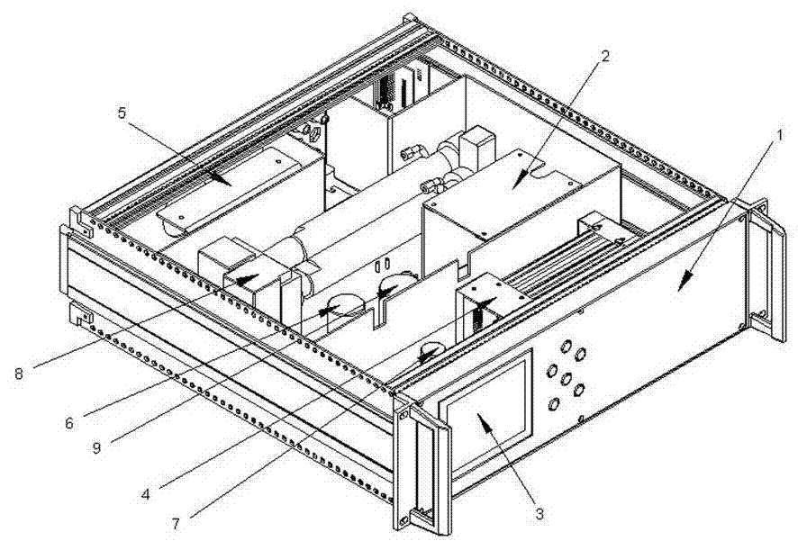
[0033] figure 1 It is a structural layout diagram of the flue gas analyzer in the embodiment of the present invention, as shown in the figure, including a chassis 1, a heating control unit 2, an output display unit 3, a data acquisition and processing unit 4, and a power supply 5; a flue gas pipe is arranged in the chassis 1 The water filter device 6 is installed at the inlet of the flue gas pipeline, and the temperature sensor, pressure sensor, humidity sensor, oxygen sensor 7, and gaseous pollutant detection unit 8 are respectively installed on the flue gas pipeline; a flue gas multi-parameter The measuring chamber 9, the temperature sensor, the pressure sensor and the humidity sensor are all set in the flue gas multi-parameter measuring chamber 9.

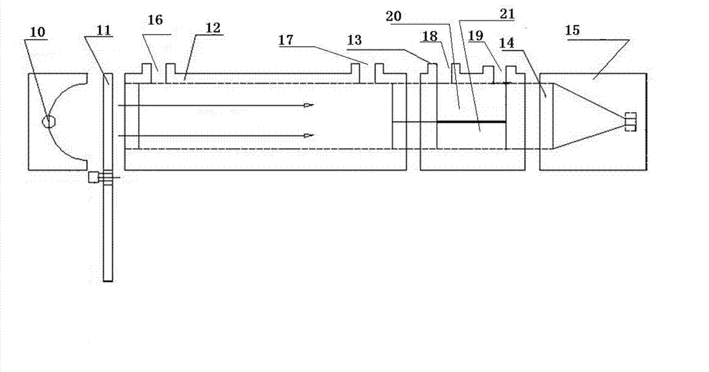
[0034]The gaseous pollutant detection unit 8 of the present embodiment includes an infrared light source 10 and a light chopper 11 arranged behind it, and is arranged in sequence along the optical path behind the light chopper t...

Embodiment 2

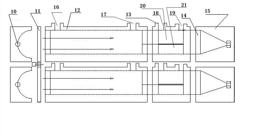
[0038] Such as image 3 As shown, in order to improve the utilization efficiency of the flue gas analyzer, two gaseous pollutant detection units 8 are arranged in parallel. The standard gas and select the corresponding detection sensor can be preferably packaged NO and CO standard gas.

Embodiment 3

[0040] The detection sensor 15 has a measurement range of 0~100~3000 mg / m 3 (dual-range) NO sensor; the reference cell 21 encapsulates NO standard gas. The data acquisition and processing unit includes a front-end control system, a circuit system, and a software analysis and calculation system; the output display unit includes a display screen, buttons, a communication unit, and a communication serial port. The water filtering device 6 is a water filtering membrane, which can block the passage of liquid water in the flue gas and protect the sensors in the cabinet. The heating control unit 2 heats the flue gas pipeline inside the cabinet to ensure that the system is in a constant temperature state. After the flue gas enters the chassis, the NO concentration can be measured after the temperature sensor, pressure sensor, humidity sensor, and oxygen sensor measure various background parameters.

[0041] Selection of the length of the absorption cell 12: it is related to the abso...


PUM

PropertyMeasurementUnit
Lengthaaaaaaaaaa

Abstract

The invention belongs to the field of low- concentration flue gas infra-red analyzers and corresponding detection methods and provides a low-concentration flue gas infra-red analyzer which is high in both precision and reliability. The flue gas analyzer adopts the structure that a gaseous contaminant detecting unit 8 comprises an infrared light source 10 and a chopper 11 behind the infrared light source 10, as well as an absorption cell 12, a measuring gas chamber 13, a light filter 14 and a detection sensor 15 which are arranged along the light path behind the chopper 11; an absorption cell sample gas inlet 16 and an absorption cell sample gas outlet 17 are formed on the absorption cell 12; and the measuring gas chamber 13 is divided into a sample cell 20 and a reference cell 21 in the light path direction so as to measure the flue gas in a high-precision manner. According to the invention, a non-dispersion infrared monochromatic source is utilized to shine the sample gas, so as to realize quantitative and accurate analysis of the to-be-tested sample gas. The infra-red analyzer and the detection method, provided by the invention, are suitable for measuring a low-concentration NO flue gas, and can also be used for the detection of low-concentration CO, CO2 and other flue gases.

Description

technical field [0001] The invention belongs to the field of flue gas monitoring equipment, in particular to a low-concentration flue gas infrared analyzer and a detection method. Background technique [0002] Most of the existing low-concentration gas on-line detection methods use non-dispersive infrared absorption photometry. The basic principle is: after the sample gas is irradiated by a non-dispersive infrared monochromatic light source, the molecules in the sample will absorb light of certain wavelengths; the light that is not absorbed reaches the detector. After the detector detects the light intensity, it generates an AC voltage signal. After the signal is amplified and processed, it is analyzed by computer calculation to obtain the corresponding absorbance value of the gas. Since the absorbance is proportional to the concentration of the component in the sample, the sample gas to be tested can be quantitatively and accurately analyzed by using the size and spectrum ...

Claims


Application Information

Patent Timeline
IPC IPC(8): G01N21/35G01N21/3504
Inventor 刘德允陈莹范黎锋陈清孙明伟李浙英王玉龙徐成亚
Owner NANJING ASSEN ENVIRONMENT TECH
Why Eureka
Try Eureka