System and technology for cleaning flue gas

A flue gas purification system, raw flue gas technology, applied in the direction of air quality improvement, chemical instruments and methods, dispersed particle separation, etc., can solve the problems of high transportation and storage costs, reduced catalyst activity, harsh use conditions, etc., to achieve technological The process is simple and optimized, the economic cost is reduced, and the effect of reducing the economic cost

Active Publication Date: 2013-01-02
BEIJING ZHONGNENG NUOTAI ENERGY SAVING & ENVIRONMENTAL PROTECTION CO LTD
View PDF4 Cites 11 Cited by
  • Summary
  • Abstract
  • Description
  • Claims
  • Application Information

AI Technical Summary

Problems solved by technology

During this reaction process, because the reaction temperature is too high and the components in the flue gas are complicated, if sulfur is contained, SO is easy to be produced. 3 , on the one hand, it is easy to poison the catalyst, on the other hand, it is easy to react with excess NH 3 Forms corrosive and viscous NH 4 HSO 4 , leading to blockage and corrosion of the tail flue equip

Method used


Image

  • System and technology for cleaning flue gas

Examples


Embodiment 1

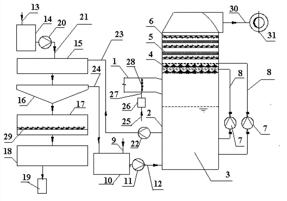
[0037] Such as figure 1 As shown, a flue gas purification system includes a connected raw flue gas input pipe 1, an absorption tower 2 and a net flue gas discharge device, and also includes an oxidation device connected to the raw flue gas input pipe 1, and an absorption tower 2 connected absorbent supply device and absorption liquid regeneration recovery device, in which:

[0038] In the absorption tower 2, a slurry pool 3, an absorbent spray layer 4, a demister layer 5, and a demister flushing water layer 6 are arranged from bottom to top;

[0039] An absorbent slurry circulation pump 7 is arranged outside the absorption tower 2, and the absorbent slurry circulation pump 7 is connected to the slurry pool 3 and the absorbent spray layer 4 through the absorbent slurry circulation pipeline 8;

[0040] The absorbent supply device includes an absorbent delivery pipeline 9, an absorbent slurry tank 10 connected to the absorbent delivery pipeline 9, an absorbent slurry input pump ...

Embodiment 2

[0067] Such as figure 1 As shown, the setting and distribution of a flue gas purification system are the same as in Embodiment 1.

[0068] Apply the flue gas purification system of the present invention to carry out flue gas purification treatment, the same as embodiment 1, except the following steps:

[0069] In step (1), the source of ozone generation is oxygen.

Embodiment 3

[0071] Such as figure 1 As shown, the setting and distribution of a flue gas purification system are the same as in Embodiment 1.

[0072] Apply the flue gas purification system of the present invention to carry out flue gas purification treatment, the same as embodiment 1, except the following steps:

[0073] In the step (2), the absorbent is sodium hydroxide;

[0074] In the step (4), the regeneration agent is quicklime.


PUM


Abstract

The invention relates to a technology for cleaning flue gas. The system comprises a raw flue gas input pipe, an absorption tower and a clean flue gas discharge device, wherein the raw flue gas input pipe, the absorption tower and the clean flue gas discharge device are connected. The system also comprises an oxidation device connected to the raw flue gas input pipe, an absorbent feeding device and an absorption liquid regenerating and recovery device, wherein the absorbent feeding device and the absorption liquid regenerating are connected to the absorption tower. A slurry tank, an absorbent spraying layer and a demister layer are arranged in the absorption tower from bottom to top. The technology adopts a sodium-based absorbent to realize removal of nitrogen and sulphur pollutants in flue gas at a low temperature or a normal temperature. The system has a novel design and the technology has simple and environmentally friendly processes, realizes recycling integrated purification treatment on flue gas, realizes synchronous efficient desulfuration and denitration by the same process route, avoids secondary pollution on the environment in full recovery and treatment on later-stage products, is conducive to reduction of an economic cost, and is suitable for purification treatment on flue gas or industrial tail gas produced by a metallurgical chemical industry and a coal-fired power generation industry mainly discharging sulfur and nitrogen oxides as pollutants.

Description

technical field [0001] The invention relates to flue gas purification technology for sulfur and nitrogen pollutants produced in the fields of power generation, metallurgy and chemical industry, and in particular to a flue gas purification system and purification process for removing sulfur and nitrogen pollutants at low temperature or normal temperature. Background technique [0002] At present, the flue gas or industrial tail gas discharged from coal-fired power generation, metallurgy, chemical industry and other industries contains oxides of sulfur and nitrogen (SO 2 , NOx) and become the main source of air and soil pollution. There are many treatment technologies for these flue gases or industrial tail gases, among which, sulfur dioxide (SO 2 ) treatment methods mainly include limestone method, ammonia method, and double alkali method, and the treatment methods for nitrogen oxides (NOx) mainly include selective catalytic reduction (SCR) method, selective non-catalytic re...

Claims


Application Information

Patent Timeline
IPC IPC(8): B01D53/80B01D53/60
CPCY02A50/20
Inventor 艾淑艳
Owner BEIJING ZHONGNENG NUOTAI ENERGY SAVING & ENVIRONMENTAL PROTECTION CO LTD
Why Eureka
Try Eureka