Method for desorbing residual carbon in siliceous dust by means of oxygen-enriched calcination and device therefor

A technology of removing and silica fume, applied in chemical instruments and methods, silicon oxide, silicon dioxide, etc., can solve the problem that the removal efficiency of residual carbon is not obvious, shorten the calcination time, ensure the constant diameter, improve the The effect of oxidation rate

Inactive Publication Date: 2013-01-02
ANHUI UNIV OF SCI & TECH
View PDF5 Cites 9 Cited by
  • Summary
  • Abstract
  • Description
  • Claims
  • Application Information

AI Technical Summary

Problems solved by technology

The removal efficiency of flotation washing method for carbon residue is not obvious

Method used


Image

  • Method for desorbing residual carbon in siliceous dust by means of oxygen-enriched calcination and device therefor

Examples


Embodiment 1

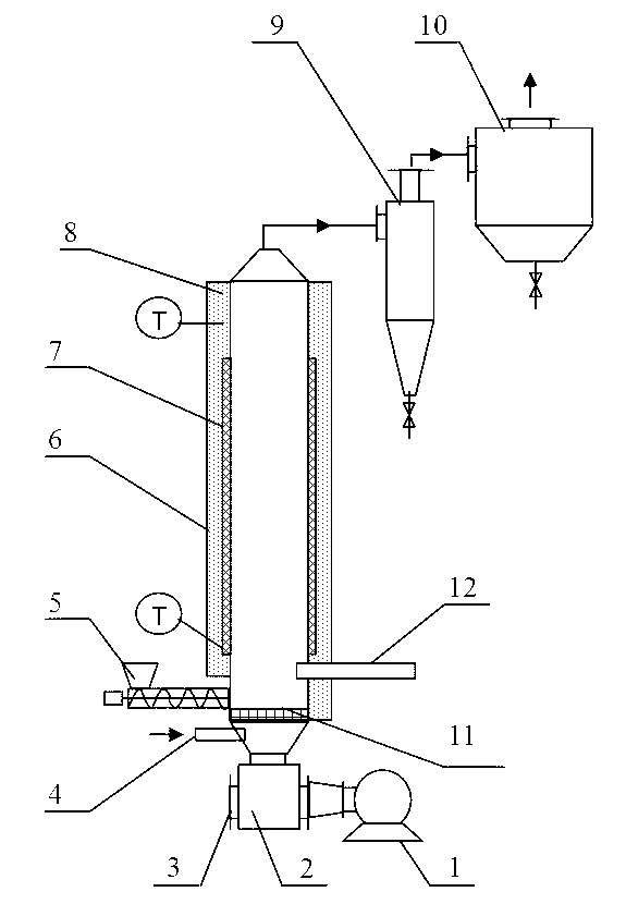
[0036] The shell of the fluidized bed calcination tower 8 is welded by refractory steel, and refractory bricks are built in the steel shell; the diameter of the effective space in the fluidized bed calcination tower 8 is 1400 mm, and the effective height is 12000 mm. A gas delivery pipe 12 is provided at the bottom of the fluidized bed calcination tower 8. The gas delivery pipe 12 transports natural gas (or coal gas) into the tower, and the natural gas is burned to provide heat to ensure that the temperature inside the tower is 720°C during the calcination process. The outer periphery of the fluidized bed calcination tower 8 is wrapped with an insulating layer 6, the thickness of the insulating layer 6 is 260 mm, so as to effectively prevent heat loss in the tower. Thermocouples are respectively installed at the upper and lower parts of the fluidized bed calciner 8 for measuring and controlling the temperature inside the fluidized bed calciner 8 to keep at 720°C.

[0037] A ba...

Embodiment 2

[0042] The fluidized bed calcination tower 8 is made of a corundum tube with an inner diameter of 100mm and a length of 1200mm. An electric heater 7 with a total power of 4Kw is installed around the outside of the fluidized bed calcination tower 8 to ensure that the temperature inside the tower is 760°C during the calcination process. . The insulation layer 6 is wrapped around the electric heater 7 and the fluidized bed calcining tower 8, and the thickness of the insulation layer 6 is 300mm, so as to effectively prevent heat loss in the tower. Thermocouples are respectively installed on the upper and lower parts of the fluidized bed calciner 8 to measure and control the temperature of the fluidized bed calciner 8 to keep at 760°C.

[0043] The bottom of the fluidized bed calciner 8 is provided with a cube-shaped housing base 2 with a side length of 400 mm. The upper part of the base 2 is provided with a round hole with a diameter of 120 mm, that is, an air outlet, which commun...


PUM

PropertyMeasurementUnit
particle sizeaaaaaaaaaa

Abstract

The invention belongs to the technical field of the removal of residual carbon in siliceous dust, and particularly relates to a method for desorbing residual carbon in siliceous dust by means of oxygen-enriched calcination and a device for desorbing the residual carbon in the siliceous dust by means of oxygen-enriched calcination. The removing method provided by the invention comprises the step of calcining the siliceous dust which contains the impurities and is under the fluidized state for 1-2minitues under the temperature of 600-800DEG C and the condition of oxygen enrichment, wherein the condition of oxygen enrichment means that the oxygen mole fraction in the gas is 30-34% in the process of calcining. The removing device provided by the invention comprises a fluidized bed calcining tower, a burning mechanism, a temperature measurement mechanism, a blasting mechanism, a material transporting mechanism, an oxygen supply mechanism and a product collecting mechanism. The invention adopts a fluidized bed calcining technology under the state of oxygen enrichment, and the oxidation speed of the residual carbon in the siliceous dust can be effectively accelerated in the process of calcining under the state of oxygen enrichment, so that the calcining time can be shortened; and the calcining can be carried out under the state of fluidization, so that the fusion and the bonding coalescence among silica particulates in the siliceous dust can be effectively avoided, and the diameters of the fine particulates can be guaranteed to be invariable.

Description

technical field [0001] The invention belongs to the technical field of removing residual carbon in silica fume, and in particular relates to an oxygen-enriched calcination removal method and a removal device for residual carbon in silica fume. Background technique [0002] Silica fume, also known as microsilica fume, is a large amount of highly volatile SiO produced in the reduction electric furnace when ferrosilicon and silicon are smelted. 2 and Si gas are rapidly oxidized and condensed by air, and the amorphous fine particles are taken out of the furnace by the flue gas, the main component of which is SiO 2 , has excellent pozzolanic properties. The production of ferrosilicon (FeSi75) per ton can produce 200-250kg of micro-silicon fume. [0003] The micro-silica fume particles are extremely fine, the particle size is less than 1 μm, accounting for more than 80%, the average particle size is 0.1-0.15 μm, and the specific surface area is greater than 15m 2 / g, which is d...

Claims


Application Information

Patent Timeline
Patent Type & Authority Applications(China)
IPC IPC(8): C01B33/18B01J6/00
Inventor 陈明功李广程万亚丽王珊余水情颜凌燕
Owner ANHUI UNIV OF SCI & TECH
Why Eureka
Try Eureka