Methyl nitrite recovery method during CO coupling dimethyl oxalate synthesis process

A technology of methyl nitrite and reflux ratio, applied in the directions of nitrite preparation, organic chemistry, etc., can solve the problem of not providing methyl nitrite recovery and other problems, and achieve the effects of reducing loss, improving utilization rate, and good technical effect.

Inactive Publication Date: 2013-02-06
CHINA PETROLEUM & CHEM CORP +1
View PDF5 Cites 11 Cited by
  • Summary
  • Abstract
  • Description
  • Claims
  • Application Information

AI Technical Summary

Problems solved by technology

The recovery of methyl nitrite

Method used


Image

  • Methyl nitrite recovery method during CO coupling dimethyl oxalate synthesis process
  • Methyl nitrite recovery method during CO coupling dimethyl oxalate synthesis process

Examples


Embodiment 1

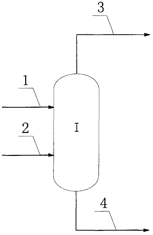
[0026] The number of rectifying tower I trays is 15, and the gas phase output of regeneration tower is that stream 1 is passed into the upper middle part of rectifying tower, promptly enters rectifying tower I by the 4th plate, and stream 1 feed temperature is 40 ℃; The noncondensable gas discharged from the chemical reactor is absorbed by the tail gas absorption tower, and the material in the bottom of the tower is a liquid stream 2, and the liquid stream 2 is passed into the middle and lower part of the rectification tower, that is, enters the rectification tower 1 by the 6th plate, and the stream 2 Feed temperature 30°C. The temperature at the top of the tower is 38°C, the temperature at the bottom of the tower is 94°C, the pressure at the tower is 250kPa, and the reflux ratio is 2. The top of the tower is separated to obtain a stream 3 containing methyl nitrite, and the tower still obtains a stream 4 containing methanol and waste water.

[0027] The condenser load per ton...

Embodiment 2

[0032] As in Example 1, the difference is that the gas phase discharge of the regeneration tower is that stream 1 enters the upper middle part of rectification tower 1, that is, enters rectification tower 1 from the third block, and the feed temperature is 43 ° C; liquid stream 2 enters rectification The middle and lower part of the tower enters the rectification tower I from the 10th plate, and the feed temperature is 22°C. The temperature at the top of the tower is 14°C, the temperature at the bottom of the tower is 90°C, the pressure at the tower is 250kPa, and the reflux ratio is 0.3.

[0033] The condenser load per ton of methyl nitrite recovered is 0.15MW, and the reboiler load is 0.43MW. The recovery of methyl nitrite was 75%. Supplement nitric oxide at 30 kg / t ethylene glycol.

[0034] The molar percentages of the stream components are shown in Table 2.

[0035] Table 2

[0036] components

Embodiment 3

[0038] As embodiment 2, difference is that the plate number of rectifying tower 1 is 30, and stream 1 enters rectifying tower by the 5th plate, and stream 2 enters rectifying tower by the 20th plate. The temperature at the top of the tower is 18°C, the temperature at the bottom of the tower is 92°C, the pressure at the tower is 250kPa, and the reflux ratio is 0.5.

[0039]The condenser load per ton of methyl nitrite recovered is 0.20MW, and the reboiler load is 0.44MW. The recovery rate of methyl nitrite was 95%. Supplement nitric oxide at 4 kg / t ethylene glycol.

[0040] The molar percentages of the stream components are shown in Table 3.

[0041] table 3

[0042] components


PUM


Abstract

The invention provides a methyl nitrite recovery method during a CO coupling dimethyl oxalate synthesis process. A gas-phase material containing methyl nitrite is delivered into an upper-middle part of a rectification tower; a liquid-phase material and a gas-phase material containing methyl nitrite are delivered into the rectification tower; a tower-top material contains methyl nitrite, and a tower-kettle material contains methanol and water; a tower plate number of the rectification tower is 10-50, the tower kettle temperature is 50 DEG C to 200 DEG C, a tower top temperature is -10 DEG C to 100 DEG C, a reflux ratio is 0.2-3.0, and an operation pressure is 50-400kPa. With the methyl nitrite recovery method provided by the invention, methyl nitrite loss can be reduced, methyl nitrite utilization rate can be improved, and cost can be reduced.

Description

technical field [0001] The invention relates to the production field of dimethyl oxalate, in particular to a method for recovering methyl nitrite in the process of CO coupling to synthesize dimethyl oxalate. Background technique [0002] In recent years, due to rising oil prices, the coal chemical industry has developed rapidly. Among them, the route of producing ethylene glycol from coal has received special attention at home and abroad. The process first generates dimethyl oxalate from carbon monoxide and methyl nitrite under the action of a palladium catalyst, and then produces ethylene glycol by gas-phase reaction of dimethyl oxalate and hydrogen in the presence of a hydrogenation catalyst. [0003] As an important intermediate product, methyl nitrite is first prepared by reaction formula (1) by nitric oxide, methyl alcohol and oxygen, and then when methyl nitrite and carbon monoxide generate dimethyl oxalate, byproduct nitric oxide (reaction formula (2 )), thus formin...

Claims


Application Information

Patent Timeline
IPC IPC(8): C07C203/00C07C201/04
Inventor 周莹李勇石锋汪永福俞旭波李艳明
Owner CHINA PETROLEUM & CHEM CORP
Why Eureka
Try Eureka