Flue gas ammonia desulfurization and deslagging system

A technology of ammonia desulfurization and flue gas pre-dust removal, applied in separation methods, chemical instruments and methods, filtration loops, etc., can solve the problems of high ammonia escape rate, large loss of absorbent, and difficulty in handling, and reduce the ammonia escape rate. , The effect of reducing floor space and high ammonia utilization

Inactive Publication Date: 2013-03-27
武汉钢铁有限公司
View PDF4 Cites 13 Cited by
  • Summary
  • Abstract
  • Description
  • Claims
  • Application Information

AI Technical Summary

Problems solved by technology

[0004] However, on the one hand, the wet ammonia desulfurization method generally has high ammonia escape rate and long plume, which causes problems such as large loss of absorbent, low ammonia utilization rate, and low recovery rate of ammonium sulfate products; on the other hand, the sintering flue gas carries There is a lot of dust. After being purified by the dust collector in the machine head, the particle size of the uncollected dust is mostly 3um, which is very fine and difficult to clean.
In the ammonia-ammonium sulfate desulfurization system, the non-discharging solution, the suspended matter brought in by ammonia water and process water, and the soot and ash in the flue gas mainly absorbed by the circulating slurry cannot be removed in time. enrichment, thereby affecting the quality of the by-product ammonium sulfate and the stable operation of the system
Filtration or sedimentation can be used to remove ash and dust, but because the main component of smoke is inorganic particles, the particle size is small, the sedimentation time is long, the liquid-solid interface is not obvious, a large sedimentation tank is required, and the separation effect is not good
Secondly, the particle size of the ash in the concentrated solution is fine, and it cannot meet the requirements of dehydration equipment such as plate and frame filter presses. The concentrated solution cannot be dehydrated normally, which makes subsequent treatment difficult.

Method used


Image

  • Flue gas ammonia desulfurization and deslagging system

Examples


Embodiment Construction

[0020] The present invention will be further described in detail below in conjunction with the accompanying drawings and specific embodiments.

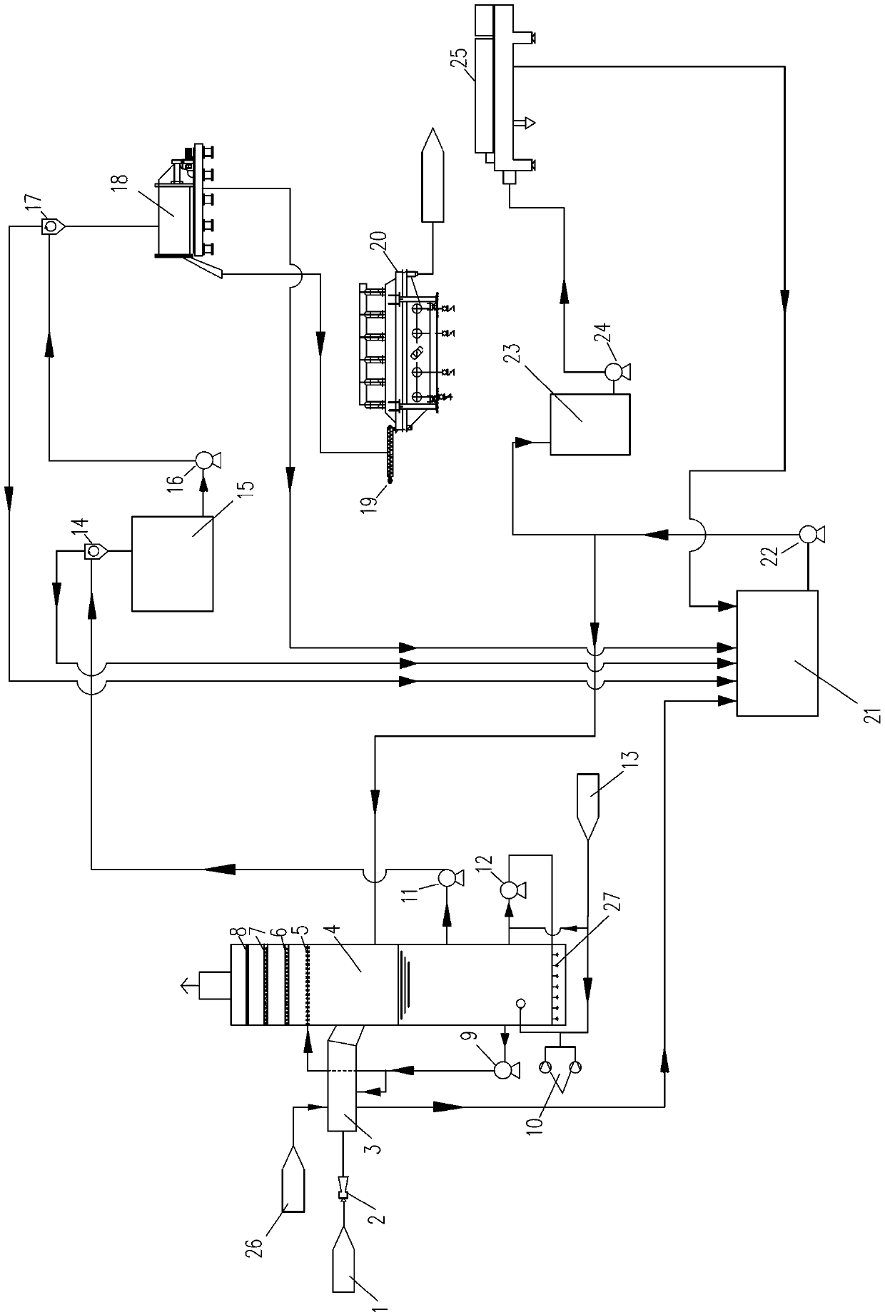
[0021] The flue gas ammonia desulfurization and slag removal system shown in the figure is mainly composed of the flue gas desulfurization subsystem, the ammonium sulfate separation subsystem and the ammonium sulfate slag removal subsystem.

[0022] The flue gas desulfurization subsystem has an absorption tower 4. Between the top flue gas outlet and the side wall flue gas inlet of the absorption tower 4, a wire mesh defoaming device 8, a mist removal device 7, a water washing device 6 and an absorption tower are sequentially arranged from top to bottom. Agent spraying device 5, a booster fan 2, a flue gas pre-dust removal and cooling device 3 are arranged in sequence between the flue gas conveying pipeline 1 and the flue gas inlet of the absorption tower 4, and the flue gas pre-dust removal and cooling device 3 is equipped with a proce...


PUM


Abstract

The invention discloses a flue gas ammonia desulfurization and deslagging system. The flue gas ammonia desulphurization and deslagging system comprises a flue gas desulfurization sub-system, an ammonium sulfate separation sub-system and an ammonium sulfate deslagging sub-system; the flue gas desulfurization sub-system comprises an absorption tower and a flue gas pre-dedusting cooling device arranged at the position of a flue gas inlet of the absorption tower; the ammonium sulfate separation sub-system comprises a primary cyclone, a secondary cyclone, a dehydration centrifugal machine and a fluidized drying bed which are sequentially connected with one another; the ammonium sulfate deslagging sub-system comprises a filtrate tank, a mixing dosing tank and a filter press which are sequentially connected with one another; and a slurry outlet of the absorption tower is connected with the primary cyclone, a purified liquor outlet of the primary cyclone, a purified liquor outlet of the secondary cyclone and a liquid outlet of the dehydration centrifugal machine are connected with the filtrate tank, and accordingly, the three sub-systems are connected into a whole. By means of the flue gas ammonia desulfurization and deslagging system, ammonia escape amount can be reduced, the phenomenon of acid rain can be effectively relieved, utilization ratios of absorbents are increased, recovery rates of ammonium sulfate products are increased, qualities of the ammonium sulfate products are improved, occupied space areas are small, space is saved, and the system can be generally used in ammonia flue gas desulfurization of thermal power generation and sintering flue gases.

Description

technical field [0001] The invention relates to a flue gas purification treatment device for thermal power generation and iron and steel industry, in particular to a flue gas ammonia desulfurization and slag removal system. Background technique [0002] Coal is mainly used as fuel in thermal power generation and steel industry. While pulverized coal combustion provides necessary heat source and power resource, it will also bring serious sulfur dioxide SO 2 pollute. According to statistics, the total amount of sulfur dioxide emitted by coal-fired power plants in my country is as high as 25.49 million tons every year, and the resulting acid rain area is close to 40% of the country's land area, which has brought huge losses to my country's ecological environment and industrial and agricultural production. Therefore, to fundamentally control the sulfur dioxide SO2 in the sintering flue gas of coal-fired power stations 2 emissions are imminent. [0003] At present, for the des...

Claims


Application Information

Patent Timeline
Patent Type & Authority Applications(China)
IPC IPC(8): B01D53/80B01D53/50B01D36/04
Inventor 汤静芳莫亚平靖汪建郑建新孔德友吴志清李富智张九红吴英
Owner 武汉钢铁有限公司
Why Eureka
Try Eureka