Cu-doping modified TiO2 photocatalyst and preparation method thereof

A photocatalyst, catalyst technology, applied in catalyst activation/preparation, chemical instruments and methods, physical/chemical process catalysts, etc., can solve the problems of expensive equipment, difficult to reuse, complex recovery, etc., to increase adsorption capacity and adsorption capacity , Improve the degradation rate, the effect of high controllability

Inactive Publication Date: 2013-04-03
RESEARCH INSTITUTE OF TSINGHUA UNIVERSITY IN SHENZHEN
View PDF2 Cites 15 Cited by
  • Summary
  • Abstract
  • Description
  • Claims
  • Application Information

AI Technical Summary

Problems solved by technology

[0004] In order to overcome the chemical method to synthesize doped modified TiO 2 Due to the limitations brought by nanotubes, some researchers also prepared Cu-Ti and Fe-Ti alloy films on conductive glass substrates by magnetron sputtering, and then grown Cu-doped and Fe-doped films by electrochemical anodic oxidation. Modified Cu-Ti-O and Fe-Ti-O nanotube arrays, but this method is expensive and complicated, and the film quality is difficult to guarantee
There are also researchers who have prepared one-dimensional nanostructured TiO on TiTa, TiMn, TiZrNb and other alloy flake substrates. 2 nanotube array films, however, the one-dimensional nanostructures prepared by the above method with doped modified TiO 2 Nanotube arrays, the specific surface area is relatively small, therefore, it is still not conducive to the increase of the adsorption amount of catalytic degradation products and the efficient use of sunlight
[0005] In addition, in the nanostructured TiO that uses nanopowders, nanofilms, etc. as wastewater organic matter to degrade 2 When using photocatalysts, there are also problems such as complicated recycling and difficulty in reusing. Therefore, TiO with such nanostructures is limited. 2 The scope of application in the field of photocatalyst

Method used


Image

  • Cu-doping modified TiO2 photocatalyst and preparation method thereof
  • Cu-doping modified TiO2 photocatalyst and preparation method thereof
  • Cu-doping modified TiO2 photocatalyst and preparation method thereof

Examples


preparation example Construction

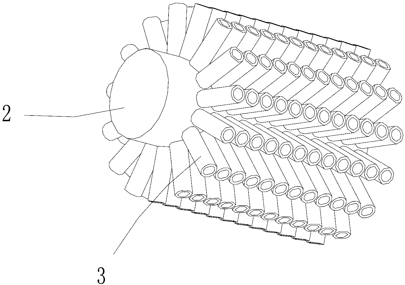
[0030] The invention provides a Cu-doped modified TiO 2 Photocatalyst and its preparation method, using electrochemical anodic oxidation method to directly prepare Cu-doped modified TiO with two-dimensional structure, highly ordered arrangement and strong visible light response performance on CuTi alloy wire or alloy rod substrate 2 Photocatalyst, which can increase the adsorption of catalytic degradation products and enhance TiO 2 Utilization efficiency of the solar spectrum by photocatalysts to promote TiO 2 Applications in the field of photocatalysis.

[0031] In this application, the term "crystallization" means that when TiO is annealed at a certain temperature 2 Structural transformation of nanotubes from amorphous to crystalline phase. The term "precursor" refers to TiO 2 Samples of nanotube array films without annealing and crystallization.

[0032] Using the two-dimensional structure of the present invention and Cu-doped TiO 2photocatalyst, added TiO 2 The spec...

Embodiment 1

[0034] In this example 1, Cu-doped TiO with a two-dimensional structure 2 A method for preparing a nanotube array, comprising the following steps:

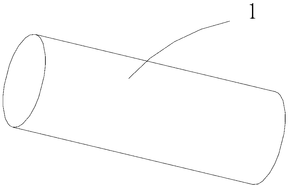
[0035] (1) See figure 1 , a Cu5-Ti95 alloy wire substrate 1 with a diameter of 3 mm and a length of 20 mm is ground and polished with metallographic sandpaper, and the substrate 1 is prepared by an arc melting method;

[0036] (2) Clean the alloy wire obtained in step (1) ultrasonically in acetone for 15 minutes, then ultrasonically clean it in absolute ethanol for 5 to 15 minutes, and finally rinse it with distilled water for 3 to 5 times. Clean the Cu5-Ti95 alloy wire Purge and dry with inert gas (such as nitrogen or argon, etc.) for later use. In this embodiment 1, the inert gas adopts nitrogen;

[0037] (3) Weigh 5.55gNH 4 Dissolve F in 15ml deionized water and stir with a magnetic stirrer to make NH 4 F is completely dissolved, and then mixed with 485ml formamide to obtain an electrolyte;

[0038] (4) At room temperatur...

Embodiment 2

[0044] In this Example 2, Cu-doped TiO with a two-dimensional structure 2 A method for preparing a nanotube array, comprising the following steps:

[0045] Except for the voltage of step (4) and the annealing temperature of step (7), other implementation steps are the same as in Example 1. The voltage of step (4) is: a DC constant voltage of 30V; the annealing temperature of step (7) is 550°C.

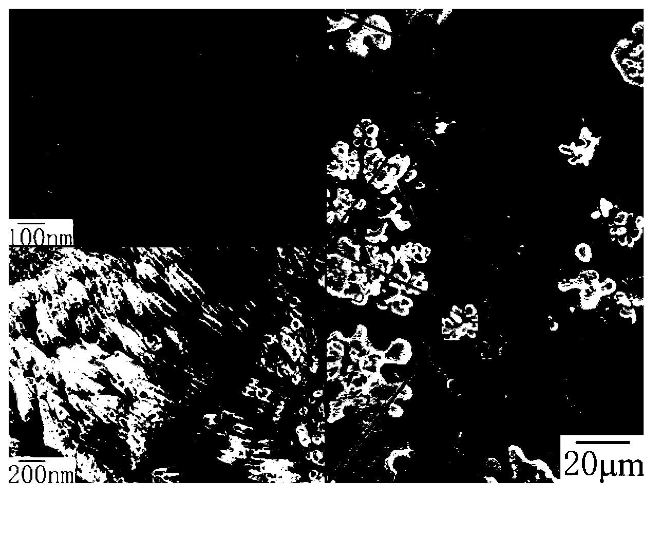
[0046] The two-dimensional structure Cu-doped modified TiO prepared in Example 2 2 Nanotube arrays whose structural units are Cu-doped TiO 2 Nanotubes, and there is a layered structure, in the large black area, Cu-doped TiO 2 The length, diameter and wall thickness of nanotubes are about 200~300nm, 40~50nm, 5~10nm, respectively. While in the petal-shaped region, Cu-doped TiO 2 The length, diameter and wall thickness of nanotubes are about 500-800nm, 40-50nm and 5-10nm, respectively. Cu-doped modified TiO prepared in Example 2 2 The absorption band edge of the nanotube array in t...


PUM

PropertyMeasurementUnit
diameteraaaaaaaaaa
lengthaaaaaaaaaa
diameteraaaaaaaaaa

Abstract

The invention discloses a Cu-doping modified TiO2 photocatalyst. The Cu-doping modified TiO2 photocatalyst grows on a copper-titanium alloy wire or bar base body and has a two-dimensional structure on the peripheral surface of the copper-titanium alloy wire or bar base body, and the structural unit of the Cu-doping modified TiO2 photocatalyst is a Cu-doping TiO2 nanotube. The invention also discloses a preparation method of the Cu-doping modified TiO2 photocatalyst. The preparation method can be used for directly growing a Cu-doping TiO2 nanotube array which has the two-dimensional structure and higher visible light response property on the copper-titanium alloy wire or bar base body through an electrochemical anode oxidation method. The Cu-doping TiO2 photocatalyst with the two-dimensional structure, which is disclosed by the invention, enlarges the specific area of a TiO2 photocatalyst and effectively extends the forbidden bandwidth of the TiO2 photocatalyst, thereby outstandingly enhancing the adsorptive capacity on a degradation product and obtaining the high-efficiency absorption on a solar spectrum; and the Cu-doping TiO2 photocatalyst is conductive to improving the visible light catalytic activity and has the advantages of good recoverability of the TiO2 photocatalyst, simple process, low cost and high controllable degree.

Description

technical field [0001] The invention relates to a titanium dioxide photocatalyst, in particular to a Cu-doped modified TiO with a two-dimensional (2D) structure 2 Nanotube arrays and methods of making them. Background technique [0002] Titanium dioxide (TiO 2 ) nanotube arrays have been widely used in the field of photocatalysis due to their excellent physical and chemical properties. However, due to TiO 2 The bandgap width of the solar cell is relatively wide, about 3.0eV~3.2eV, so that only less than 5% of the solar spectrum in the ultraviolet region can be absorbed and utilized, thus severely restricting its efficient absorption of sunlight. To overcome TiO 2 This defect makes it have better visible light response performance. Researchers from various countries have carried out extensive and in-depth research on this, and the most effective method is to change its electronic and energy band structure by means of doping. Such as transition metal elements (such as Cr,...

Claims


Application Information

Patent Timeline
Patent Type & Authority Applications(China)
IPC IPC(8): B01J23/72B01J37/34C25D11/26
Inventor 马清陈建军杨建张维丽王晓伟符冬菊
Owner RESEARCH INSTITUTE OF TSINGHUA UNIVERSITY IN SHENZHEN
Why Eureka
Try Eureka