Incineration disposal method for high-salinity wastewater

A treatment method and high-salt technology, which are applied in combustion methods, steam generation methods using heat carriers, incinerators, etc., can solve the problems of coking in incinerators, high salt content in flue gas, waste heat recovery devices and flue gas treatment equipment. Blockage and other problems, to avoid the effect of re-dissolution

Inactive Publication Date: 2013-04-03
BMEI
View PDF5 Cites 22 Cited by
  • Summary
  • Abstract
  • Description
  • Claims
  • Application Information

AI Technical Summary

Problems solved by technology

[0005] (1) During the incineration process, the salt in the wastewater is easy to adhere to the inner wall of the incinerator, causing the incinerator to coke;
[0006] (2) The flue gas produced by incineration has a high salt content, which will crystallize and precipitate during the temperature drop process, resulting in blockage of the waste heat recovery device and flue gas treatment equipment, affecting the normal and continuous operation of the process;
[0007] (3) The salt content in the waste water produced by flue gas treatment is still high, which needs to be further incinerated in the furnace

Method used


Image

  • Incineration disposal method for high-salinity wastewater
  • Incineration disposal method for high-salinity wastewater
  • Incineration disposal method for high-salinity wastewater

Examples


Embodiment 1

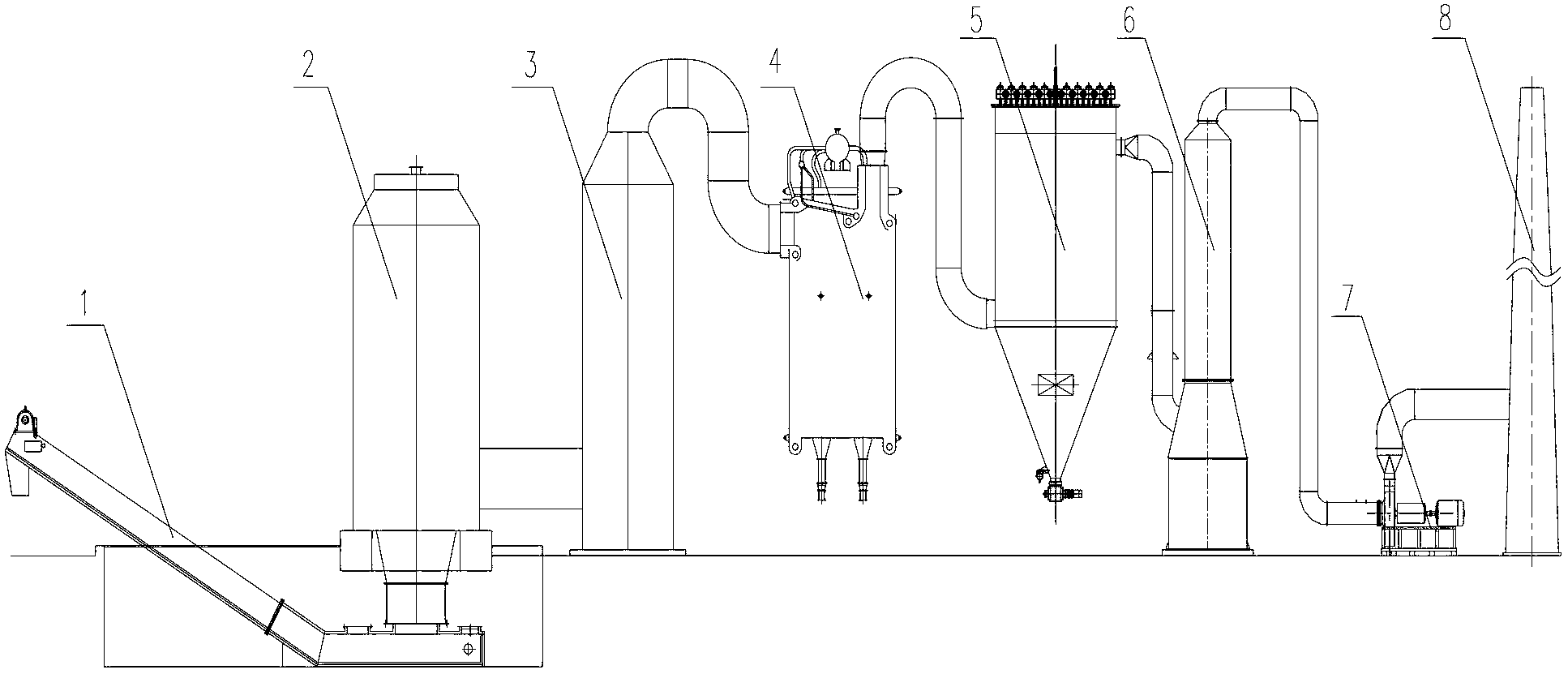
[0029] Such as figure 1 As shown, the main equipment of the high-salt wastewater incineration treatment method of the present invention includes: a combustion chamber 2, a combustion chamber 3, a dry slag remover 1, a waste heat boiler 4, a bag filter 5, a deacidification tower 6, an induction The fan 7 and the chimney 8 are communicated with each other through the flue, and the whole system maintains a slight negative pressure operation.

[0030] The steps of the present invention are as follows: high-salt waste liquid is sprayed into the first combustion chamber 2 after being atomized by compressed air through the spray gun arranged on the top of the first combustion chamber 2 . The first combustion chamber 2 is equipped with a light oil burner and an air supply system to maintain the temperature in the furnace at 600-700°C and fully evaporate the high-salt wastewater. The precipitated salt falls into the dry slag remover 1 located at the bottom of the first combustion cham...

Embodiment 2

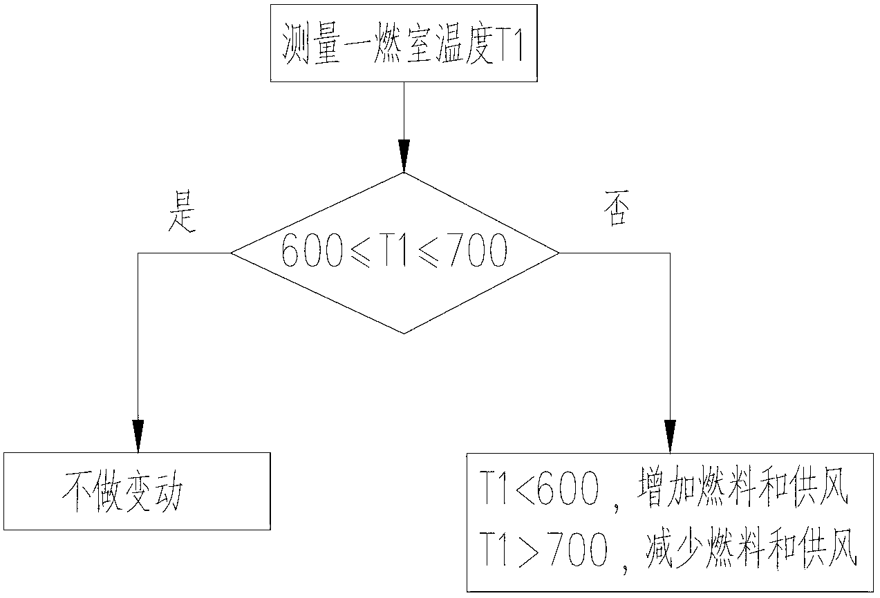
[0032] Such as figure 2 As shown, it is a schematic diagram of the control of two temperature conditions in the first combustion chamber. A temperature sensor is installed at the flue gas outlet of the first combustion chamber 2 to monitor the flue gas temperature T1 in the first combustion chamber 2 in real time, and the oil supply volume of the burner and the air supply volume of the fan are controlled by interlocking. When T1 is in the range of 600-700°C, the oil supply volume and air supply volume remain unchanged. When T1700°C, the temperature in the furnace is too high, and the salt in the high-salt wastewater may melt at high temperature. At this time, reduce the oil supply and air supply.

Embodiment 3

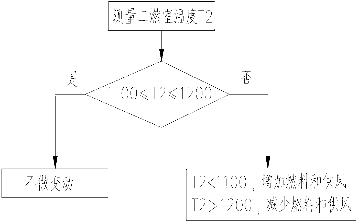
[0034] Such as image 3 Shown is a schematic diagram of temperature control in the second combustion chamber 3 . A temperature sensor is installed at the flue gas outlet of the second combustion chamber 3 to monitor the temperature T2 of the flue gas in the second combustion chamber 3 in real time, and the oil supply volume of the burner and the air supply volume of the fan are controlled by interlocking. When T2 is in the range of 1100-1200°C, the oil supply volume and air supply volume remain unchanged. When T21200°C, the temperature in the furnace is too high, there is a risk of increasing nitrogen oxides in the flue gas, and the economy is poor. At this time, reduce the oil supply and air supply.


PUM


Abstract

The invention discloses an incineration disposal method for high-salinity wastewater. The high-salinity wastewater is sprayed into a combustion chamber I after being atomized by utilizing a waste liquid spray gun through compressed air. In the combustion chamber I, the consumption of auxiliary fuel and air supply volume are controlled through temperature feedback to keep furnace temperature at 600-700 DEG C. Smoke generated in the combustion chamber I enters a combustion chamber II under the action of an induced draft fan; in the combustion chamber II, the consumption of the auxiliary fuel and the air supply volume are controlled through the temperature feedback to keep the furnace temperature at 1100-1200 DEG C, and moreover, the standing time of the smoke is longer than 2 seconds. Smoke coming out from the combustion chamber II enters a waste heat boiler, and the heat of the smoke is recycled through heat exchange. Smoke coming out from the waste heat boiler is respectively dedusted and deacidified through a bag type dust collector and a smoke deacidification unit, and then, is discharged on the standard. According to the incineration disposal method for the high-salinity wastewater, not only can saline matter in the high-salinity wastewater be separated out through the evaporation of water without coking but also hazardous organic matters in the smoke can be fully destroyed by fire.

Description

technical field [0001] The invention relates to the technical field of environmental protection, in particular to an incineration treatment method for high-salt wastewater. Background technique [0002] High-salt wastewater refers to wastewater containing organic matter and at least a mass fraction of total dissolved solids (TDS) greater than or equal to 3.5%, including high-salt domestic wastewater and high-salt industrial wastewater. It mainly comes from industrial production that directly uses seawater, domestic water and food processing plants, pharmaceutical plants, chemical plants, and oil and natural gas collection and processing. In addition to containing a large amount of inorganic salts, such as Cl - , S 2 o 4 - , Na + , Ca 2 + In addition to plasma, it also contains organic pollutants, which are hazardous wastes and must be treated before they can be discharged. [0003] At present, the incineration method is commonly used to treat high-salt wastewater. Th...

Claims


Application Information

Patent Timeline
Patent Type & Authority Applications(China)
IPC IPC(8): F23G7/04F22B1/18
Inventor 张绍坤李金龙韩晓强崔天鑫汪洪伟何辉
Owner BMEI
Why Eureka
Try Eureka