Enhanced optical microfluidic sensor device coated with dielectric layer and method

A sensing device and enhanced technology, applied in the measurement of phase influence characteristics, etc., can solve the problems of not considering thick-walled microtubes, the limitation of the object to be detected, and limit the applicability of analysis, so as to improve the detection limit, simplify the calibration, reduce the Small volume effect

Active Publication Date: 2013-04-17
TIANJIN UNIV
View PDF3 Cites 10 Cited by
  • Summary
  • Abstract
  • Description
  • Claims
  • Application Information

AI Technical Summary

Problems solved by technology

Due to the chemical interaction between the substance to be tested and the coated polymer layer, the object to be detected is limited and only applicable to a limited single gas, and the analysis is carried out for thin-walled microtubes with a wall thickness of 3 μm, without considering thick-walled microtubes, further limits the applicability of the above analysis

Method used


Image

  • Enhanced optical microfluidic sensor device coated with dielectric layer and method
  • Enhanced optical microfluidic sensor device coated with dielectric layer and method
  • Enhanced optical microfluidic sensor device coated with dielectric layer and method

Examples


Embodiment 1

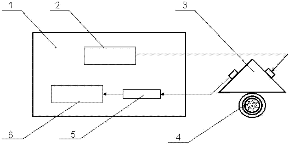
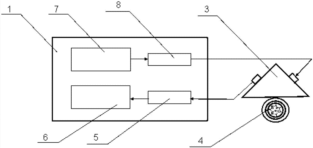
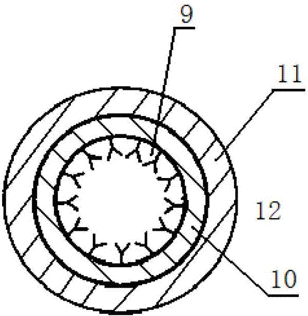
[0041] like figure 1 As shown, an enhanced optical microfluidic sensing device coated with a dielectric layer includes a spectral analysis device 1 , a prism coupling device 3 , and an enhanced optical microfluidic sensor 4 . The spectrum analysis device 1 is composed of a tunable laser 2 , a photodetector 5 and a signal processing unit 6 . The light wave output by the tunable laser 2 is coupled into the enhanced optical microfluidic sensor 4 through the prism coupling device 3, and a WGM resonance mode is formed in the enhanced optical microfluidic sensor, such as image 3 As shown, the biological detection reagent 9 is pre-cured on the inner wall surface of the medium layer 10 with a high refractive index of the enhanced optical microfluidic sensor 4. When the detected biomolecules flow through, the reaction with the biological detection reagent 9 will change the medium layer 10. The refractive index of the inner wall surface and the resonant wavelength of the resonant mode...

Embodiment 2

[0042] Embodiment 2: Fabrication method of an enhanced optical microfluidic sensor coated with a medium layer on the inner surface of the microtube

[0043] Firstly, a quartz tube with an outer diameter of 25 mm and a wall thickness of 4 mm is drawn into a quartz microtube by using an optical fiber drawing tower. The outer diameter of the quartz microtube is 250 μm and the wall thickness is 20 μm; secondly, polystyrene is dissolved in xylene organic solvent , the concentration is 0.1g / ml, then the polystyrene solution is filled into the drawn microtube; finally, the microtube is filled with a hot air flow at 45°C to evaporate the organic solvent, thereby A polystyrene medium layer is formed on the surface of the inner wall of the micropipe, and the thickness of the medium layer is 2.3 μm. It is made into an enhanced optical microfluidic sensor. The refractive index of the polystyrene material in the 1550nm band is 1.59-1.60.

Embodiment 3

[0044] Example 3: An Enhanced Photomicrofluidic Sensing Method Coating a High Refractive Index Medium Layer on the Inner Surface of Microtubes

[0045] like figure 1 , the light emitted by the tunable laser 2 is coupled into the enhanced optical microfluidic sensor 4 through the prism coupling device 3 to generate a WGM resonance mode. The inner surface of the high refractive index medium layer of the enhanced optical microfluidic sensor 4 is pre-cured biological detection reagent 9, and the resonance wavelength of the whispering gallery resonant mode of the enhanced optical microfluidic sensor satisfies

[0046] 2πr eff no eff =2πr eff (n 1 n 1 +n 2 n 2 +n 3 n 3 +n 4 n 4 ) = mλ (1)

[0047] In the formula, r eff is the effective radius, n eff is the effective refractive index, η 1 , η 2 , η 3 , η 4 Respectively, the optical field energy distribution coefficients of the biological detection reagent 9 cured in the tube of the enhanced optical microfluidic sens...


PUM

PropertyMeasurementUnit
thicknessaaaaaaaaaa
sizeaaaaaaaaaa
thicknessaaaaaaaaaa

Abstract

The invention discloses an enhanced optical microfluidic sensor device coated with a dielectric layer. The enhanced optical microfluidic sensor device coated with the dielectric layer comprises a spectrum analyzing device, a prism coupling device, and an enhanced optical microfluidic sensor of which the inner wall is coated with a high-refractivity dielectric layer, wherein light output by a light source is coupled into the enhanced optical microfluidic sensor through the prism coupling device; the enhanced optical microfluidic sensor is a sensing passage and a transferring passage; and the spectrum analyzing device is used for collecting and analyzing the wavelength of light coupled and output by the enhanced optical microfluidic sensor so as to realize sensing. The enhanced optical microfluidic sensor uses a microtube of which the inner surface is coated with the high-refractivity dielectric layer as an optical resonant cavity, so that the detection sensitivity is improved, and the optical resonant cavity, the sensing passage and the fluid transferring passage are integrated, with an advantage of integration; and the enhanced optical microfluidic sensor device coated with the dielectric layer is applicable to various ways and can achieve mass production by an existing technology.

Description

technical field [0001] The invention relates to a high-sensitivity optical microfluidic resonance sensing device and method, in particular to an enhanced optical microfluidic sensing device and method in which the inner surface of a microtube is coated with a high refractive index medium layer. Background technique [0002] Label-free microfluidic biosensors based on optical refractive index detection can directly measure molecular interactions, avoiding the need for special fluorescent markers, complicated labeling, weakened biological activity due to labeling, and interference with the reaction itself. and other adverse effects, it has broad application prospects in life sciences, medical research and other fields. [0003] The optical microresonator uses total reflection to completely confine the light in the microcavity, forming a standing wave to generate a whispering gallery resonance mode (Whisper Gallery Mode, WGM). Because of total reflection, the leakage loss is ve...

Claims


Application Information

Patent Timeline
Patent Type & Authority Applications(China)
IPC IPC(8): G01N21/41
Inventor 江俊峰刘铁根刘琨张晶于哲姬强陈文杰
Owner TIANJIN UNIV
Why Eureka
Try Eureka