Hydrogen enriching exhaust recirculator for waste heat recovery of internal-combustion engine

A technology of exhaust gas recirculation and waste heat recovery, applied in exhaust devices, exhaust gas recirculation, internal combustion piston engines, etc., can solve the problem of reducing the power output characteristics of the engine, increasing the distance of the exhaust valve port of the reactor, and unstable engine power output. and other problems, to achieve the effect of compact structure, easy installation in real vehicles, and fast reaction speed of hydrogen production

Active Publication Date: 2013-05-01
浙江和夏科技股份有限公司
View PDF9 Cites 7 Cited by
  • Summary
  • Abstract
  • Description
  • Claims
  • Application Information

AI Technical Summary

Problems solved by technology

Such a solution will inevitably reduce the power output characteristics of the engine
[0007] 3. In patent 94116320.2 and patent 99122107.9, the heat required by the reactor is obtained through heat transfer on the wall surface of the exhaust gas, which makes the catalytic reaction bed heat up slowly and affects the hydrogen production efficiency
[0008] 4. Patent 94116320.2 adopts the integrated design of hydrogen generator and muffler, which will inevitably increase the distance from the reactor to the engine exhaust valve port, increase the exhaust heat loss, reduce the utilization efficiency of exhaust waste heat, make it difficult to heat up the reactor, and affect the efficiency of catalytic hydrogen production
[0009] 5. Due to the technical characteristics of the above patents, its efficient hydrogen production operation is limited to heavy load conditions with high engine exhaust temperatures
When the engine is running for a long time, the lack of hydrogen and the change of the added concentration will bring about the hidden danger of unstable power output of the engine

Method used


Image

  • Hydrogen enriching exhaust recirculator for waste heat recovery of internal-combustion engine
  • Hydrogen enriching exhaust recirculator for waste heat recovery of internal-combustion engine
  • Hydrogen enriching exhaust recirculator for waste heat recovery of internal-combustion engine

Examples


Embodiment

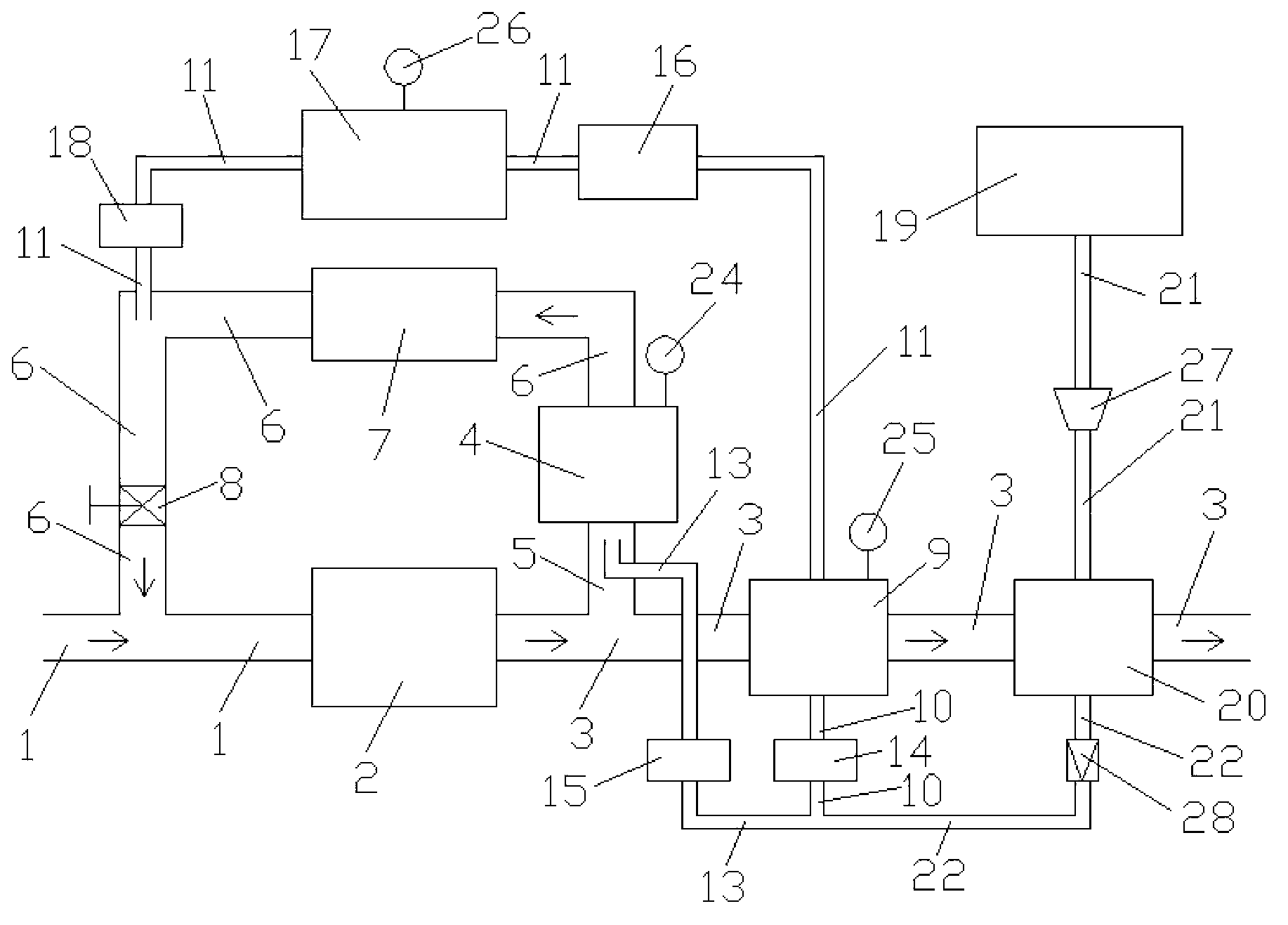
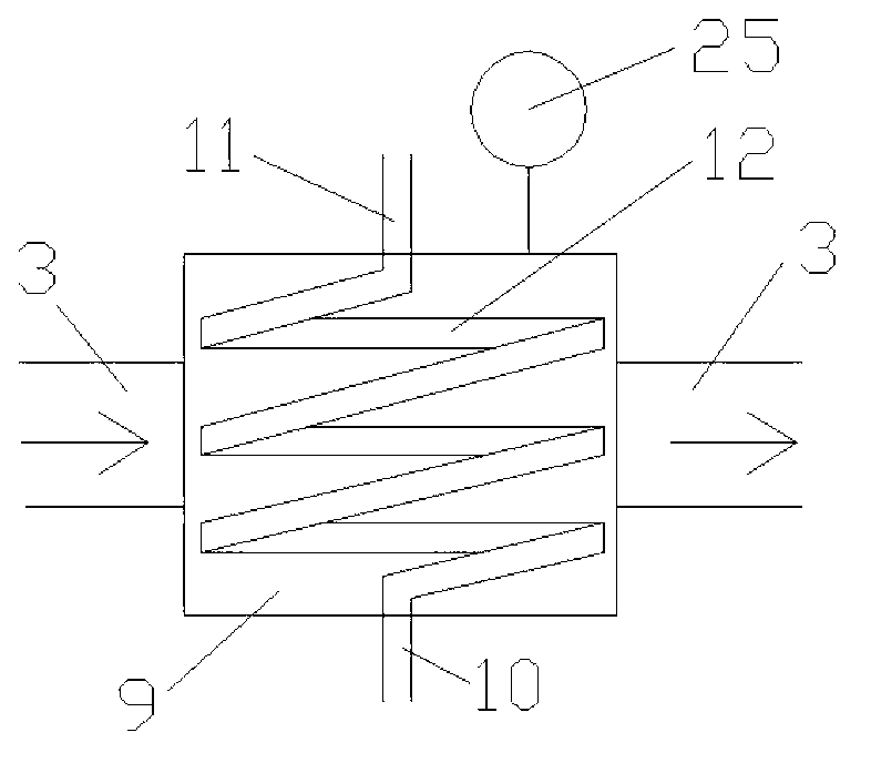
[0033] Such as figure 1 , figure 2 , image 3 and Figure 4 As shown, the present invention includes intake pipe 1, engine 2, engine exhaust pipe 3, first hydrogen generator 4, exhaust gas recirculation intake pipe 5, first hydrogen generator outlet pipe 6, exhaust gas recirculation cooler 7 , Exhaust gas recirculation control valve 8, second hydrogen generator 9, second hydrogen generator inlet pipe 10, second hydrogen generator outlet pipe 11, second heat exchange pipe 12, first hydrogen generator inlet pipe 13, Second mass flow controller 14, first mass flow controller 15, supercharger 16, hydrogen-rich gas buffer tank 17, third mass flow controller 18, hydrogen energy carrier storage tank 19, evaporator 20, evaporator flow Inlet pipe 21, evaporator outflow pipe 22, first heat exchange pipe 23, first temperature sensor 24, second temperature sensor 25, pressure sensor 26, liquid pump 27, check valve 28 and wire 29, the inlet and outlet of engine 2 The air ports are res...


PUM


Abstract

The invention relates to a hydrogen enriching exhaust recirculator which belongs to the technical field of an internal-combustion engine. The hydrogen enriching exhaust recirculator comprises an engine, hydrogen makers, a control valve, quality flow controllers, a storage tank and an evaporator. A second hydrogen maker and the evaporator are sequentially installed on an exhaust pipe of the engine, an exhaust recirculating cooler and an exhaust recirculating control valve are sequentially installed on a gas outlet pipe of the first hydrogen maker, and a pressurizer, a hydrogen enriching gas storage tank and a third quality flow controller are sequentially installed on a gas outlet pipe of the second hydrogen maker. In the working process of the engine, the combustion phase of the engine is adjusted in real time based on the working conditions of the engine, the exhaust temperature and the pressure signal feedback in the hydrogen enriching gas storage tank to control the temperature of a catalytic bed, a hydrogen-rich gas is generated in a catalytic cracking hydrogen carrier in the hydrogen maker by means of waste heat exhausted by the engine, and the hydrogen-rich gas obtained along with recirculating gas enters into the combustion chamber of the engine to combust with fuel. The hydrogen enriching exhaust recirculator provided by the invention is reasonable in design and simple in structure, and is suitable for the fields of gasoline engines, diesel engines for automobiles and ships, aero-engines and the like.

Description

technical field [0001] The present invention relates to an exhaust gas recirculation system in the technical field of internal combustion engines, in particular to a hydrogen-rich exhaust gas recirculation system for catalytically cracking hydrogen energy carriers (including methanol, ethanol, ammonia water, gasoline, etc.) by utilizing waste heat of internal combustion engines. Background technique [0002] Energy conservation and environmental protection are one of the important themes for human beings to achieve sustainable development. Given that internal combustion engines will still be the mainstream power devices for transportation in the medium and long term, reducing the fuel consumption and harmful emissions of internal combustion engines is the most effective strategy to achieve energy saving and emission reduction before the large-scale popularization of power devices. [0003] Exhaust gas recirculation technology is one of the effective means to reduce the emiss...

Claims


Application Information

Patent Timeline
Patent Type & Authority Applications(China)
IPC IPC(8): F02M25/07F02M25/12F01N5/02F02M26/36
CPCY02T10/16Y02T10/121Y02T10/12
Inventor 李铁
Owner 浙江和夏科技股份有限公司
Why Eureka
Try Eureka