Eureka AIR delivers breakthrough ideas for toughest innovation challenges, trusted by R&D personnel around the world.

Ice coating detection device for cable

A detection device and cable technology, applied in measurement devices, optical devices, instruments, etc., can solve problems such as industrial and commercial paralysis, damage to power equipment, damage to transmission line systems, etc., to solve electromagnetic compatibility problems, reduce overall cost requirements, Chemically stable effect

Inactive Publication Date: 2013-05-01
YANTAI RAYTRON TECH
View PDF5 Cites 8 Cited by
  • Summary
  • Abstract
  • Description
  • Claims
  • Application Information

AI Technical Summary

Problems solved by technology

[0004] The icing load is the biggest factor that damages the transmission line system. The icing of the transmission line will cause the damage of the transmission line, such as broken strands, broken wires, collapsed towers, flashover between conductors and ground wires, short-circuit tripping, and icing dancing, which will cause harm to society and production. huge loss
There have been serious icing disasters on transmission lines at home and abroad. In December 2000, in southeastern Ukraine, the icing disaster caused damage to 300,000 concrete towers and 20,000 iron towers; in November 2005, power transmission lines in western Germany In December 2008, a blizzard hit areas near the Appalachian Mountains in the United States, causing power outages for 700,000 residents and paralysis of industries and commerce; , a rare large-scale icing in the world has affected more than a dozen provinces in southern my country. Due to the continuous rain, snow and freezing weather, large-scale icing of transmission lines has occurred, towers have been overwhelmed and collapsed and disconnected, power supply has been interrupted on a large scale, and power equipment has been damaged. Unprecedented damage, direct economic loss of more than 100 billion yuan

Method used


Image

  • Ice coating detection device for cable
  • Ice coating detection device for cable
  • Ice coating detection device for cable

Examples


Embodiment Construction

[0027] The principles and features of the present invention are described below in conjunction with the accompanying drawings, and the examples given are only used to explain the present invention, and are not intended to limit the scope of the present invention.

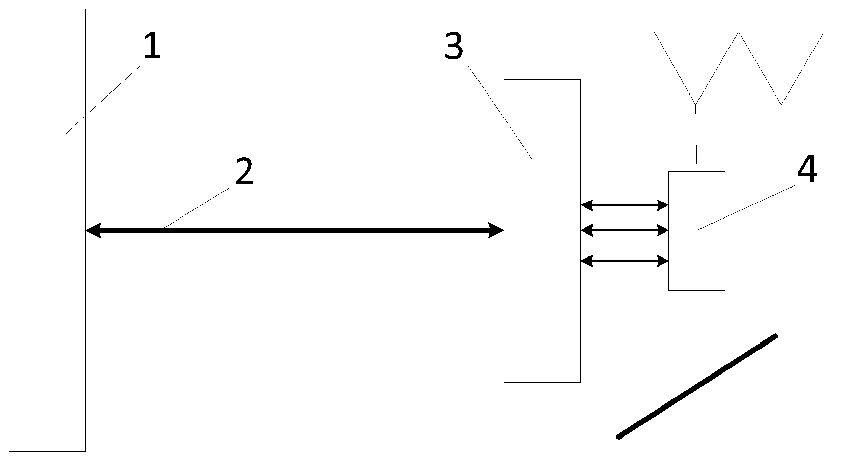
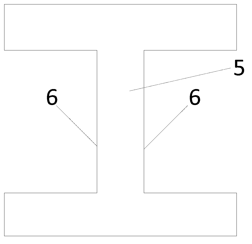
[0028] Such as figure 1 As shown, a cable icing detection device includes a fiber grating wavelength modulator 1, an optical splitter 3 and a fiber grating load cell 4, and the fiber grating wavelength modulator 1 and the optical splitter 3 pass a signal The transmission cable 2 is connected, the optical splitter 3 and the fiber grating load cell 4 are connected through a signal transmission cable, the upper end of the fiber grating load cell 4 is suspended on an object at a fixed height, and the fiber grating load cell The lower end of the load cell 4 is connected to the detected cable, and a part of the fiber grating load cell 4 is an elastic body, such as image 3 As shown, the elastic body 5 is provided with a ...


PUM


Abstract

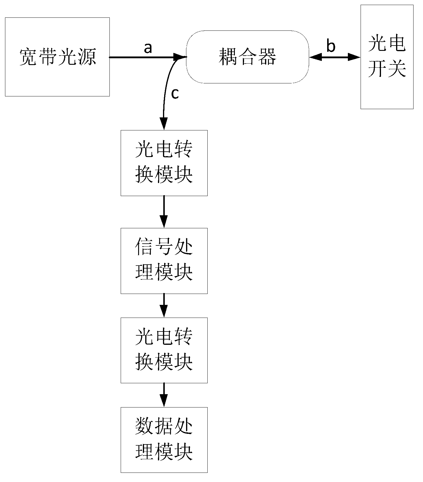
The invention relates to a weight detection device, in particular to an ice coating detection device for a cable. The ice coating detection device comprises a fiber grating wavelength modulator, an optical divider and a fiber grating weighing sensor, wherein the fiber grating wavelength modulator is connected with the optical divider through a signal transmission optical cable; the optical divider is connected with the fiber grating weighing sensor through a signal transmission optical cable; the upper end of the fiber grating weighing sensor is fixedly suspended, and the lower end of the fiber grating weighing sensor is connected with the cable; an elastic body is arranged in the middle of the fiber grating weighing sensor; the elastic body is provided with the fiber grating sensor; a broadband light source is arranged in the fiber grating wavelength modulator; the broadband light source is transmitted to the fiber grating sensor through a signal transmission optical cable; the fiber grating sensor is used for transmitting a wavelength signal of reflected light of the broadband light source to the fiber grating wavelength modulator; and the fiber grating wavelength modulator is used for obtaining the weight change of the cable according to a received wavelength signal. Due to the adoption of the ice coating detection device, the ice coating condition of the cable can be effectively detected.

Description

technical field [0001] The invention relates to a weight detection device, in particular to a cable icing detection device. Background technique [0002] Fiber Bragg grating uses the photosensitivity of the fiber material to write the incident light coherent field pattern into the fiber core by ultraviolet light exposure, and produces a periodic change in the refractive index along the core axis in the fiber core, thereby forming a permanent space. The phase grating, whose function is essentially to form a narrow-band (transmission or reflection) filter or mirror in the core. When a beam of wide-spectrum light passes through a fiber Bragg grating, the wavelength (Bragg wavelength) that satisfies the Bragg condition of the fiber Bragg grating will be reflected, and the remaining wavelengths will continue to transmit through the fiber Bragg grating. When the external parameters change, the effective refractive index and grating period of the fiber grating will change accordin...

Claims


Application Information

Patent Timeline
IPC IPC(8): G01G9/00G01B11/16
Inventor 靳占军霍佃恒张永庆张勇
Owner YANTAI RAYTRON TECH
Why Eureka
Eureka Blog
Learn More