Magnetic material and method for producing same
A technology of magnetic materials and magnets, applied in the field of magnetic materials and their manufacturing, can solve the problems of reduced magnetic properties, thermal instability, etc., and achieve the effect of high magnetic properties
- Summary
- Abstract
- Description
- Claims
- Application Information
AI Technical Summary
Problems solved by technology
Method used
Image

Examples
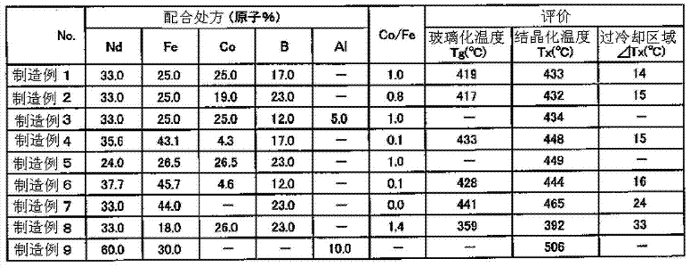
manufacture example 1~8
[0199] Production examples 1 to 8 (manufacture of amorphous metal)
[0200] Prepare monomer powders or lumps of Nd (neodymium), Fe (iron), Co (cobalt), Al (aluminum) and B (boron) according to the mixing ratio of the composition shown in Table 1, and arc The melting furnace was dissolved in an Ar (argon) atmosphere of 4 kPa (30 Torr) to produce alloys (ingots) having the composition ratios shown in Table 1.
[0201] Next, the obtained ingot was pulverized to obtain alloy granular materials (particle diameter: 0.5 to 10 mm).
[0202] Thereafter, the obtained alloy pellets were dissolved by high-frequency induction heating under an Ar atmosphere to form an alloy melt, and then the obtained alloy melt was placed under an Ar atmosphere with a single-roller device at a peripheral speed of 40 m / s. Rapid cooling is performed by flowing down the outer peripheral surface of the cooling roll. Thus, an amorphous metal is obtained.
[0203] Thereafter, the obtained amorphous metal was ...
manufacture example 9
[0204] Production of Production Example 9 (Production of Amorphous Metal)
[0205] Manufacture of Nd by gas atomization method (spray gas: Ar) 60 Fe 30 Al 10 After that, fine pulverization was carried out with a ball mill (LP-1 manufactured by Ito Seisakusho). Thus, Nd with a volume average particle diameter of 1 μm was obtained 60 Fe 30 Al 10 of powder.
[0206] [Evaluation]
[0207] Using DSC (differential scanning calorimetry: manufactured by SII, DSC6300), the crystallization temperature (Tx) of the amorphous metal obtained in each production example was measured, and when the amorphous metal was metallic glass, the glass transition temperature (Tg).
[0208] Specifically, 10 mg of an amorphous metal sample was put into an aluminum pan, and measured in an Ar atmosphere at a temperature increase rate of 40° C. / min.
[0209] In addition, when a plurality of crystallization reactions (Tx) were confirmed, the one with the lower temperature was measured as crystallizat...
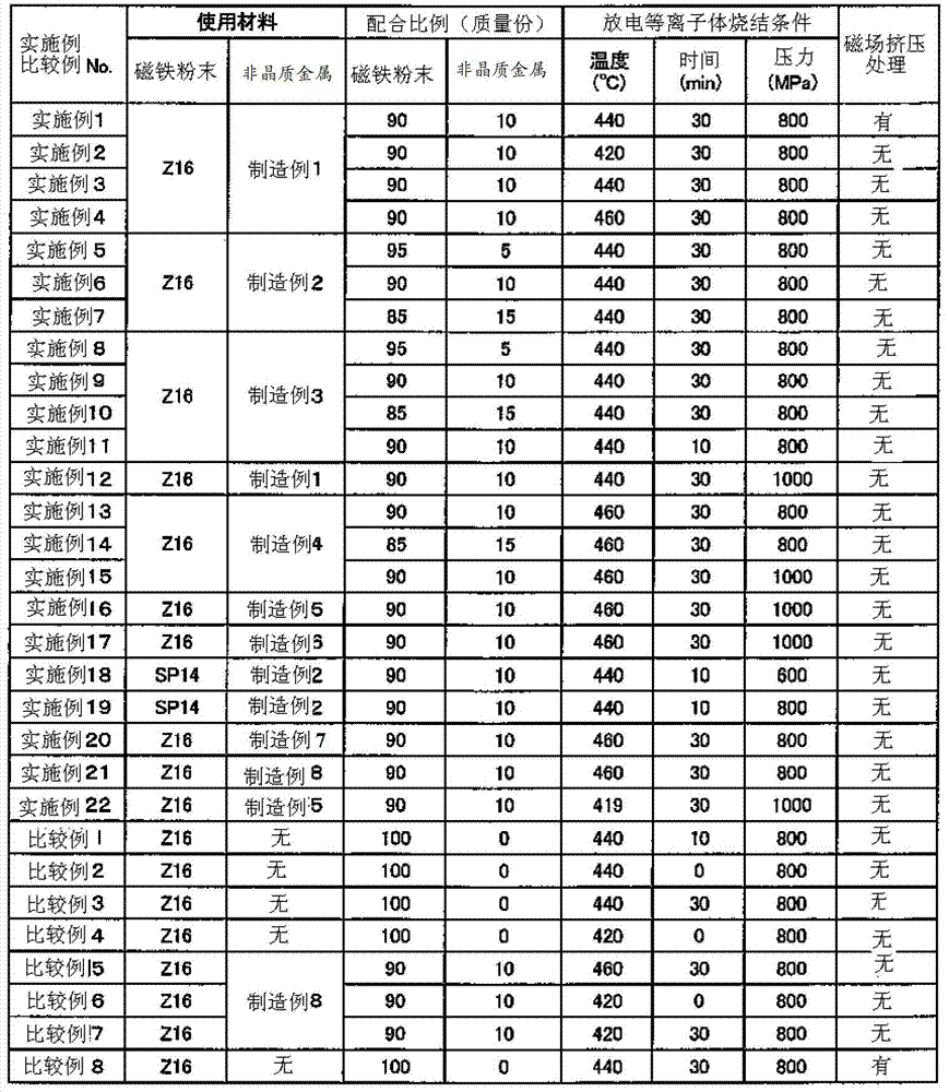
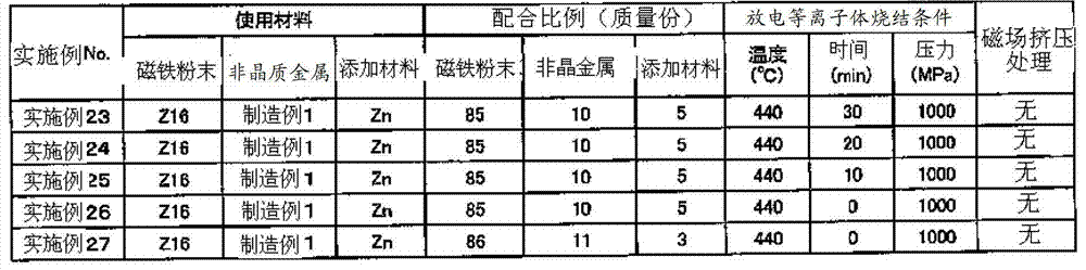
Embodiment 1
[0215] The powder of the amorphous metal obtained in Production Example 1 and Z16 (magnetic anisotropic magnet powder, Sm-Fe-N magnet (Sm 2 Fe 17 N 3 ), a decomposition temperature of 600°C, a volume average particle diameter of 3 μm, manufactured by Nichia Chemical Industry Co., Ltd.), compounded in such a way that the amorphous metal is 10% by mass relative to their total amount, and pulverized in cyclohexane A machine (FILMICS40-40 manufactured by PRIMIX) was mixed for 5 minutes at a peripheral speed of 40 m / s.
[0216] Next, it was dried in a nitrogen atmosphere to obtain a mixed powder of an amorphous metal powder and a magnet powder.
[0217] Then, extract 1.0 g of the mixed powder and fill it into a non-magnetic mold (manufactured by HOKKAIMIC, sleeve and punch material: non-magnetic cemented carbide (WC-Ni alloy), mold material: HPM75, molding size: 8mm×6mm) , using a magnetic field extrusion machine (TM-MPH8525-10T type manufactured by Tamagawa Seisakusho), under a...
PUM
| Property | Measurement | Unit |
|---|---|---|
| Curie point | aaaaa | aaaaa |
| particle diameter | aaaaa | aaaaa |
| thickness | aaaaa | aaaaa |
Abstract
Description
Claims
Application Information
 - R&D
- Intellectual Property
- Life Sciences
- Materials
- Tech Scout
- Unparalleled Data Quality
- Higher Quality Content
- 60% Fewer Hallucinations
Browse by: Latest US Patents, China's latest patents, Technical Efficacy Thesaurus, Application Domain, Technology Topic, Popular Technical Reports.
© 2025 PatSnap. All rights reserved.Legal|Privacy policy|Modern Slavery Act Transparency Statement|Sitemap|About US| Contact US: help@patsnap.com