Relay retransmission device and relay retransmission method for satellite radio frequency and optical fiber signal transmission data

A signal transmission and forwarding device technology, applied in the direction of optical fiber transmission, transmission system, electromagnetic repeater, etc., can solve the problem that multiple microwave signal frequency bands cannot be covered at the same time, the power capacity of coaxial cable is small, and the power and capacity of coaxial conversion are small etc. to achieve good anti-electromagnetic interference capability, strong confidentiality, and wide bandwidth

Inactive Publication Date: 2015-07-22
XIAN INSTITUE OF SPACE RADIO TECH +1
View PDF4 Cites 4 Cited by
  • Summary
  • Abstract
  • Description
  • Claims
  • Application Information

AI Technical Summary

Problems solved by technology

[0004] Figure 4 As shown, the frequency bands currently used by satellite communication systems are mainly C / Ku / Ka frequency bands, and the corresponding input / output multiplexers are also transponders of a specific frequency band, and the common transmission line adopted is generally a waveguide or Coaxial public transmission line, but cannot cover multiple microwave signal frequency bands at the same time
The broadband public transmission line adopts a coaxial transmission line, and the broadband signal is fed into each channel through the coaxial cable, and there is a waveguide coaxial conversion between the channel filter and the coaxial cable, and the signal transmitted in the coaxial cable is fed into the waveguide channel filter , the channel filter extracts the signal of the corresponding frequency band. The advantage of this scheme is that it is relatively easy to implement. By selecting a suitable high-frequency cable connector, the coaxial cable can transmit broadband signals from the C-band to the Ka-band. The disadvantages are: The power capacity of the coaxial cable is relatively small, and the channel filter is generally designed as a waveguide low-pass filter, which requires a waveguide-coaxial conversion to connect the channel filter and the common transmission line, and the wave-to-coaxial conversion has a small power and capacity defect

Method used


Image

  • Relay retransmission device and relay retransmission method for satellite radio frequency and optical fiber signal transmission data
  • Relay retransmission device and relay retransmission method for satellite radio frequency and optical fiber signal transmission data
  • Relay retransmission device and relay retransmission method for satellite radio frequency and optical fiber signal transmission data

Examples


Embodiment 1

[0093] The system implementation scheme is as Figure 8 As shown, it is divided into the following 9 steps:

[0094] 1. Select three channels of sine wave analog microwave signals C, Ku, and Ka, with frequencies of 6GHz, 14 GHz, and 30 GHz, respectively;

[0095] 2. Combine the three signals into one electrical signal;

[0096] 3. The combined microwave signal is phase-deflected and then input to the two arms of the Mach-Zehnder electro-optic modulator. The extinction ratio of the modulator is 20dB and the insertion loss is 5dB;

[0097] 4. A continuous wave laser produces a wavelength of 1550nm, a frequency of 1931.THz, and an emission power of 10dBm. The laser is input into a Mach-Zehnder modulator and combined with microwave signals for electro-optic modulation. The modulated spectrum is as follows: Figure 9 shown;

[0098] 5. The modulated optical signal is input to the EDFA amplifier for amplification, the amplification gain is 50dB, and the noise factor is 5dB;

...


PUM


Abstract

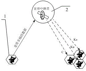
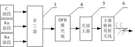
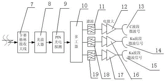
The invention discloses a relay retransmission device and a relay retransmission method for satellite radio frequency and optical fiber signal transmission data. The relay retransmission device comprises a broadband relay satellite which is connected with a broadband multi-band frequency database, or a ground launch station or a receiving station via a laser uplink and a radio frequency downlink, microwave signals in different frequency bands are modulated into a raster to be transmitted and processed, an optical carrier wave carrying multiple paths of microwave signals is launched to the relay satellite via the ground optical launch station, an optical receiving antenna of the relay satellite optically detects the received optical signal and recovers and separates the multiple paths of microwave signals, and the launch antenna transmits separated electric signals to the ground receiving station. The relay retransmission device has the advantages of simplicity, convenience in use, good confidentiality and wide satellite broadband, multi-band frequency and multi-format analog signals are directly modulated onto an optical carrier, application range of an electromagnetic frequency spectrum is widened, electromagnetic compatibility is provided, satellite carried broadcast and information distribution capability are improved, transparent radio-frequency signal retransmission is realized, and complexity for processing a satellite is reduced.

Description

technical field [0001] The invention relates to an on-star data relay and forwarding technology, in particular to a relay and forwarding device and a forwarding method for broadband and anti-interference satellite radio frequency and optical fiber signal transmission data on a star. Background technique [0002] Satellite microwave communication technology is widely used in military and civilian fields. With the development of military communication and civilian communication technology, higher and higher requirements are put forward for the forwarding capability of satellite communication signals. In particular, a very prominent feature of the future broadband communication satellite system is that it will be equipped with a huge number of multi-beam radio frequency antennas. Satellite microwave communication forwarding technology is limited by capacity, speed, electromagnetic interference, etc., and cannot meet actual requirements. [0003] In this context, people have sh...

Claims


Application Information

Patent Timeline
Patent Type & Authority Patents(China)
IPC IPC(8): H04B7/185H04B10/2575H04B10/29
Inventor 谭庆贵蒋炜赵尚弘李勇军朱子行楚兴春赵卫虎石磊
Owner XIAN INSTITUE OF SPACE RADIO TECH
Why Eureka
Try Eureka