
A kind of silicon nitride crucible and preparation method thereof

A silicon nitride crucible and silicon nitride technology, applied in the field of material science, can solve the problems of crucible cracking, easy to be corroded by silicon liquid, complex structure, etc.

Inactive Publication Date: 2014-10-15
ZHEJIANG YUHUI SOLAR ENERGY SOURCE
View PDF4 Cites 0 Cited by
  • Summary
  • Abstract
  • Description
  • Claims
  • Application Information

AI Technical Summary

Problems solved by technology

However, the quartz crucible has many disadvantages: it is infiltrated with molten silicon at high temperature and is easily eroded by the silicon liquid. Therefore, the pot bottom material or silicon ingot tends to adhere to the wall of the quartz crucible during solidification, and the expansion coefficients of quartz and silicon are different. Very large, extreme mechanical stress will either lead to crystallization defects inside the ingot, or cause the crucible to crack; and the continuous high temperature in the Czochralski single crystal will soften and deform the crucible and cannot be used again
[0004] Due to its low self-diffusion coefficient, high temperature resistance, and good chemical stability, silicon nitride is usually used as a coating material in polysilicon casting. Based on the above reasons, the prior art focuses on silicon nitride crucibles. Silicon has high stability at high temperature, but the silicon nitride crucible still has the problem of sticking to the molten silicon. By adjusting the pore size of the silicon nitride crucible surface, it has been shown that the material is not wetted by the molten silicon, but it has not yet Fully meet the production requirements, a silicon nitride / silicon oxide crucible arranged in layers improves the anti-adhesion effect, but its structure is complex, the production process is cumbersome, and the production cost is high

Method used


Image

  • A kind of silicon nitride crucible and preparation method thereof
  • A kind of silicon nitride crucible and preparation method thereof
  • A kind of silicon nitride crucible and preparation method thereof

Examples


Embodiment Construction

[0025] The core of the present invention is to provide a silicon nitride crucible, which is used for smelting silicon material in the solar energy production process. The crucible can be prepared through a simple process and low production cost. The crucible has good anti-adhesion effect, And can effectively reduce the introduction of impurities. Another core of the present invention is to provide a method for preparing the above-mentioned crucible.

[0026] In order to enable those skilled in the art to better understand the solution of the present invention, the present invention will be further described in detail below in conjunction with the accompanying drawings and embodiments.

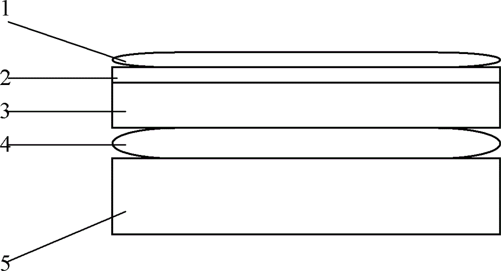
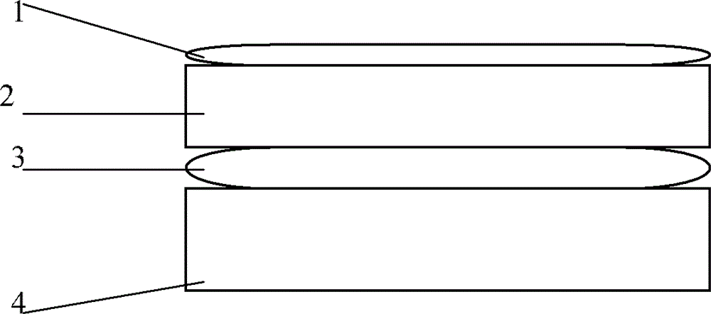
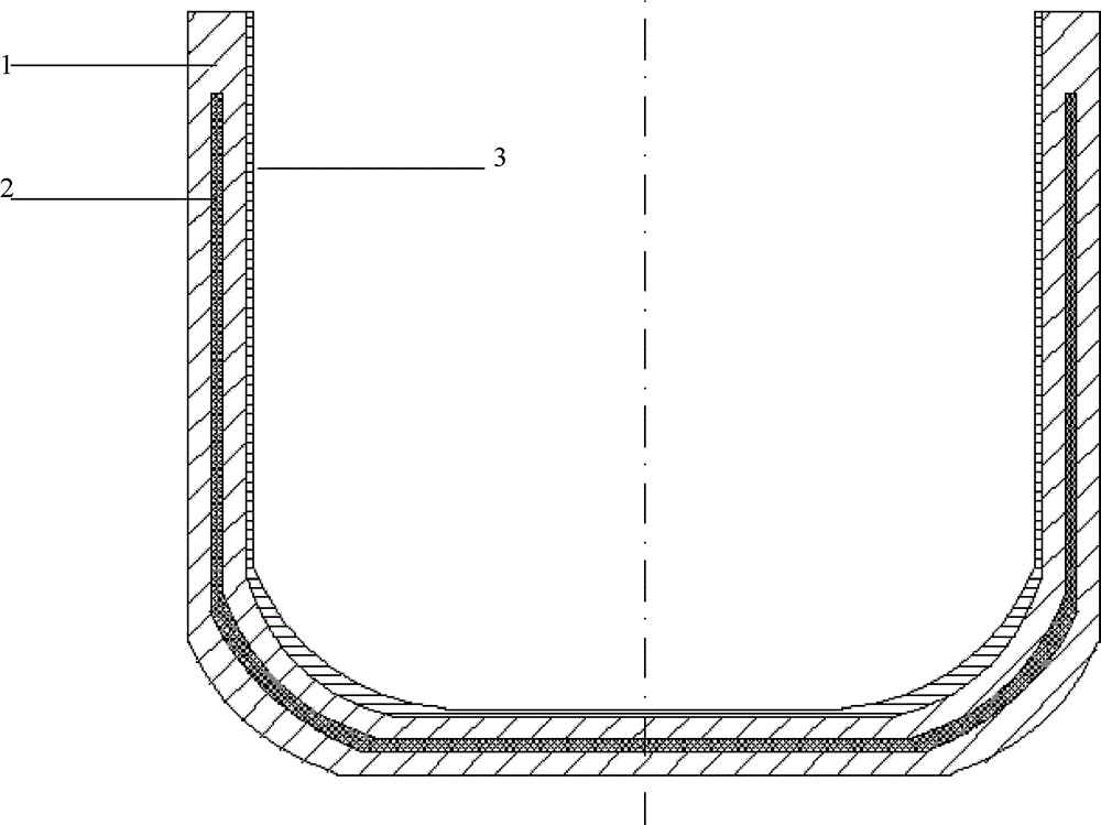
[0027] Please refer to figure 1 as well as figure 2 , figure 2 It is a schematic structural diagram of the silicon nitride crucible provided by the present invention after modeling treatment; where the number 1 is the zirconia coating, the number 2 is the inner wall layer of silicon nitrid...


PUM

PropertyMeasurementUnit
densityaaaaaaaaaa
particle sizeaaaaaaaaaa
densityaaaaaaaaaa

Abstract

The invention discloses a silicon nitride crucible. The crucible comprises a silicon nitride outer wall layer, a rich silicon layer, a silicon nitride inner wall layer and a zirconia coating from outside to inside in sequence. The outer wall layer can replace a graphite crucible to play a role of supporting. The inner wall layer can resist a certain amount of heat shock. The rich silicon layer is in a softening state under high temperature and porosity is high. When heat shock transmits to the rich silicon layer, the heat shock is released through compression and certain deformation of pores, and heat impact resistance capacity of the silicon nitride crucible is greatly enhanced. An anti-bonding layer is formed by the zirconia coating. The problem of adhesion of silicon materials and the inner wall of the crucible when the silicon materials are solidified is effectively solved, and repeated use of the crucible is possible. Meanwhile, the invention further discloses a method for manufacturing the silicon nitride crucible with the characteristics.

Description

technical field [0001] The invention relates to the field of material science, in particular to a silicon nitride crucible, and also discloses a method for preparing the crucible. Background technique [0002] Today, with the depletion of fossil energy and the increasing greenhouse effect, solar energy has huge market potential as a sustainable clean energy. Crystalline silicon cells dominate the solar cell market, and the smelting process of crystalline silicon directly affects the efficiency and cost of solar cells. [0003] At present, quartz crucibles made of high-purity silicon dioxide (SiO2) are generally used as the preferred crucible material for the production of Czochralski monocrystalline silicon, polycrystalline silicon ingots and polycrystalline silicon purification. The structure of single crystal crucible is as follows figure 1 Parts indicated by numbers 1-3. Among them, the label 1 is the barium-coated layer. The function of the barium-coated layer is that...

Claims


Application Information

Patent Timeline
Patent Type & Authority Patents(China)
IPC IPC(8): C04B35/66C04B41/85
Inventor 郭江涛王先进郑志东
Owner ZHEJIANG YUHUI SOLAR ENERGY SOURCE
Learn More