
Adhesive composition for optical components, adhesive for optical components, optical component with adhesive layer, and image display device

A technology for optical components and adhesive layers, applied in the direction of non-polymer adhesive additives, adhesive types, adhesive additives, etc., can solve the problems of uneven color, light leakage, etc., and achieve difficult foaming and color suppression Excellent effect of non-uniformity and reworkability

Active Publication Date: 2013-06-19
MITSUBISHI CHEM CORP +1
View PDF7 Cites 24 Cited by
  • Summary
  • Abstract
  • Description
  • Claims
  • Application Information

AI Technical Summary

Problems solved by technology

Furthermore, when the dimensional change occurs due to the passage of time of the polarizing plate, since the adhesive layer deforms following the dimensional change of the polarizing plate, the polymer in the adhesive layer is partially oriented, thereby causing birefringence, Causes color unevenness and light leakage such that the peripheral part of the liquid crystal display panel is brighter or darker than the center

Method used


Image

  • Adhesive composition for optical components, adhesive for optical components, optical component with adhesive layer, and image display device
  • Adhesive composition for optical components, adhesive for optical components, optical component with adhesive layer, and image display device
  • Adhesive composition for optical components, adhesive for optical components, optical component with adhesive layer, and image display device

Examples


Embodiment 14

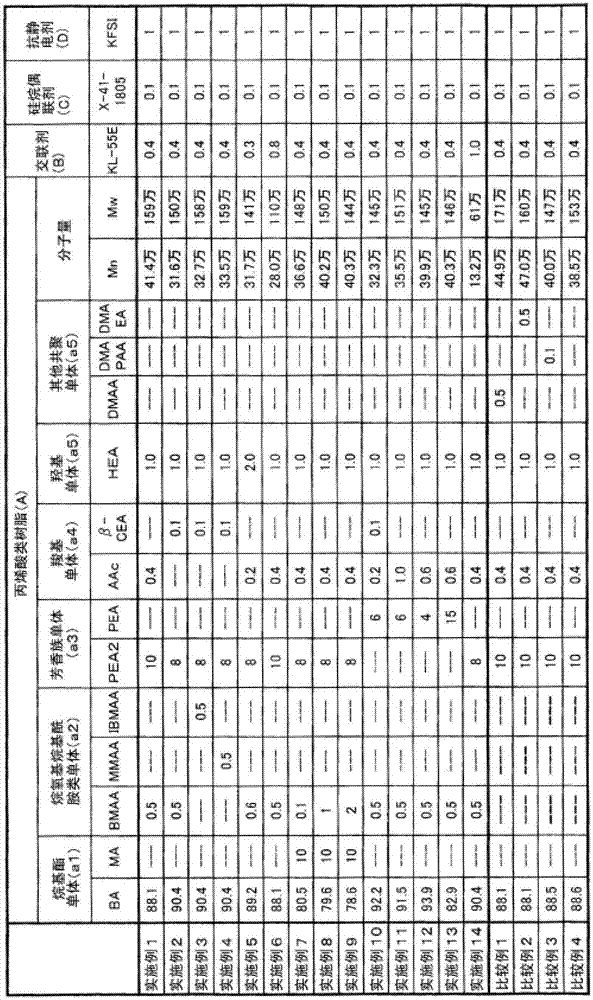
[0135]For Example 14, put 120 parts of ethyl acetate into a four-necked round-bottomed flask equipped with a reflux condenser, a stirrer, a nitrogen blowing port, and a thermometer, and heat up while stirring. When the internal temperature reaches 75°C, 0.05 parts of azobis Add all the solution of isobutyronitrile (polymerization initiator) dissolved in 5 parts of ethyl acetate, then keep the internal temperature at 74-76°C, add 90.4 parts of butyl acrylate (a1), 8 parts of phenoxydiethyl A mixed solution of diol acrylate (a3), 1 part of 2-hydroxyethyl acrylate (a5), 0.5 part of N-(n-butoxymethyl) acrylamide (a2), and 0.4 part of acrylic acid (a4) was passed through 2 It was added dropwise to the reaction system within hours. Then, after carrying out superposition|polymerization at internal temperature 74-76 degreeC for 5 hours, ethyl acetate was added, and an acrylic resin (A) solution was obtained.

[0136] In addition, for Comparative Examples 1 to 3, other copolymerizable...

Embodiment 1~14、 comparative example 1~4

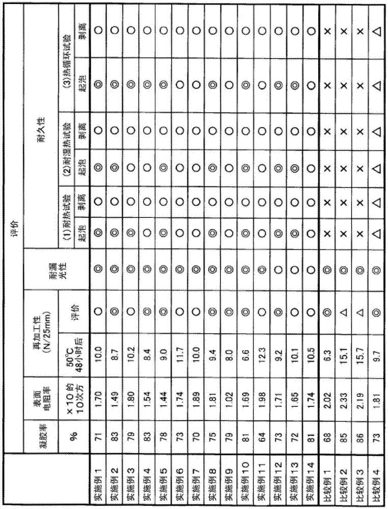
[0161] The respective compounding components prepared and prepared as described above were compounded at the ratios shown in Table 1 to prepare an adhesive composition to be an adhesive-forming material for optical parts, which was diluted with methyl ethyl ketone (viscosity [500 ~1000mPa·s (25°C)]) to prepare an adhesive composition solution.

[0162] Next, the above-mentioned adhesive composition solution was coated on a polyester-based release sheet so that the thickness after drying was 25 μm, and after drying at 90° C. for 3 minutes, the side of the formed adhesive composition layer was transferred to After coating on a polyethylene terephthalate (PET) film (thickness 38 μm), it was cured for 10 days at a temperature of 23° C. and a relative humidity of 65% to obtain a PET film with an adhesive layer.

[0163] Using the PET film with an adhesive layer obtained in this way, the gel fraction and surface resistivity were measured and evaluated by various methods shown below....


PUM


Abstract

The present invention provides an adhesive composition for optical components that is capable of achieving both reworkability and durability and that is capable of inhibiting unevenness in color and light leakage when applied to image display devices such as liquid crystal display panels. The present invention relates to an adhesive composition for optical components that contains an acrylic resin (A) obtained by copolymerizing a copolymerization component [I] containing, as the principal component thereof, an alkyl (meth)acrylate ester monomer (a1), wherein the adhesive composition is characterized by containing a N-(alkoxyalkyl)(meth)acrylamide monomer (a2) as the copolymerization component [I].

Description

technical field [0001] The present invention relates to an adhesive composition for optical members, an adhesive for optical members, an optical member with an adhesive layer, and an image display device. Specifically, it relates to optical components such as optical films (polarizing films, retardation films, optical compensation films, and brightness enhancement films) suitable for image display devices such as liquid crystal display devices, organic EL display devices, and PDPs (plasma display panels), and more Specifically, it relates to an adhesive composition for optical members for bonding an optical laminate in which a polarizing film is covered with a protective film such as a cellulose triacetate film, and a glass substrate of a liquid crystal cell, and the adhesive composition is crosslinked The resulting adhesive for optical members, an optical member with an adhesive layer formed with an adhesive layer comprising the adhesive for optical members, especially a pola...

Claims


Application Information

Patent Timeline
IPC IPC(8): C09J133/04C09J11/06C09J133/24G02B5/30G02F1/1335C09J7/22C09J7/38
CPCC09J133/26G02F1/133528C09J2203/318C09J2433/00C09J7/38C09J7/22C08F220/302C09J2301/122C08F220/20C08F220/54C08F220/06C09J133/04C09J11/06C09J133/24G02B5/30G02F1/1335
Inventor 池端晃
Owner MITSUBISHI CHEM CORP
Learn More