Lime kiln waste gas waste heat electricity generating system with by-product coal gas afterburning function

A technology for by-product gas and waste heat power generation, which is applied in waste heat treatment, steam generation methods using heat carriers, machines/engines, etc., can solve the problems of low superheated steam parameters, low system thermal efficiency, and low power generation. Steam parameters, the effect of increasing flue gas temperature and increasing power generation

Inactive Publication Date: 2013-10-09
广州智光节能环保有限公司
View PDF9 Cites 12 Cited by
  • Summary
  • Abstract
  • Description
  • Claims
  • Application Information

AI Technical Summary

Problems solved by technology

[0006] 1. The temperature of lime kiln exhaust gas is low, so the parameters of superheated steam are low, the thermal efficiency of the system is low, and the power generation is small

Method used


Image

  • Lime kiln waste gas waste heat electricity generating system with by-product coal gas afterburning function
  • Lime kiln waste gas waste heat electricity generating system with by-product coal gas afterburning function
  • Lime kiln waste gas waste heat electricity generating system with by-product coal gas afterburning function

Examples


Embodiment 1

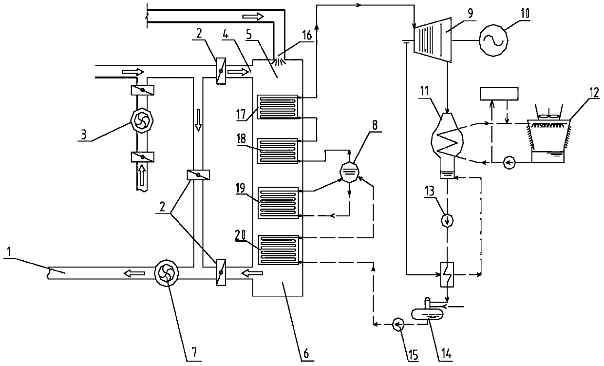
[0031] The structure of this embodiment is as figure 2 As shown, the lime kiln waste gas waste heat power generation system with by-product gas supplementary combustion includes flue gas valve 2, waste heat boiler 6, steam drum 8, steam turbine 9, generator 10, condenser 11, cooling tower 12, condensate pump 13 , a deaerator 14, a boiler feed pump 15, an induced draft fan 7, a blower 3 and a chimney 1, and a combustion furnace 5, a high-temperature superheater 17, a low-temperature superheater 18, an evaporator 19 and An economizer 20, a waste gas inlet 4 is provided on the combustion furnace 5 of the waste heat boiler 6, and a gas inlet 16 is also provided. The boiler feed pump 15 is connected with the inlet of the economizer 20, and the outlet of the economizer 20 is connected to the steam drum 8 is connected to the water inlet, the water inlet of the evaporator 19 is connected to the water outlet of the steam drum 8, the outlet of the evaporator 19 is connected to the vapo...

Embodiment 2

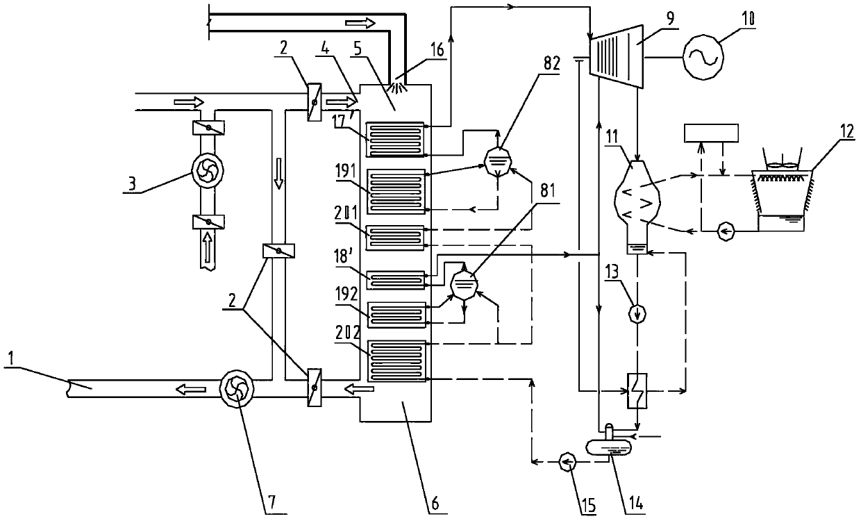
[0037] The structure of this embodiment is as image 3 As shown, the difference from Embodiment 1 is that the waste heat boiler 6 is sequentially provided with a combustion furnace 5, a high-pressure superheater 17', a high-pressure evaporator 191, a high-temperature economizer 201, a low-pressure superheater 18', a low-pressure The evaporator 192 and the low-temperature economizer 202, the steam drum is divided into a high-pressure steam drum 82 and a low-pressure steam drum 81, the boiler feed water pump 15 is connected to the inlet of the low-temperature economizer 202, and the outlet of the low-temperature economizer 202 is connected to the high-temperature economizer The inlet of 201 is connected with the water inlet of low-pressure steam drum 81, the water inlet of low-pressure evaporator 192 is connected with the water outlet of low-pressure steam drum 81, the outlet of low-pressure evaporator 192 is connected with the vapor-liquid two-phase inlet of low-pressure steam d...


PUM


Abstract

The invention discloses a lime kiln waste gas waste heat electricity generating system with a by-product coal gas afterburning function. The lime kiln waste gas waste heat electricity generating system comprises a smoke valve, a waste heat boiler, a steam pocket, a turbine, a boiler water feeding pump, a condenser, a condensate water pump, a cooling tower, a deaerator, an electricity generator, an induced draft fan, an air blower, and a chimney. A combustion hearth, a high temperature super-heater, a low temperature super-heater, an evaporator and a coal economizer are sequentially arranged in the waste heat boiler from top to bottom, an outlet of the high temperature super-heater is connected with a steam inlet of the turbine through a pipeline, the waste heat boiler is provided with a lime kiln waste gas inlet and a by-product coal gas inlet, and an air blowing opening is additionally formed in an air inlet smoke pipe so as to provide oxygen needed by coal gas burning. The lime kiln waste gas waste heat electricity generating system with the by-product coal gas afterburning function can greatly increase smoke temperature, so that the temperature and the pressure of superheated steam at the inlet of the turbine are increased, and electricity generating capacity is improved.

Description

technical field [0001] The invention relates to a waste heat power generation system, in particular to a lime kiln waste gas waste heat power generation system with supplemental combustion of by-product gas. Background technique [0002] The existing lime kiln waste gas waste heat power generation system such as figure 1 As shown, it includes flue gas valve 2, waste heat boiler 6, boiler feed water pump 15, deaerator 14, steam turbine 9, condenser 11, steam drum 8, and high temperature superheater 17 is arranged in waste heat boiler 6 from top to bottom , evaporator 19 and economizer 20. [0003] Waste heat boiler 6 imports waste gas from lime kiln preheater, and the inlet temperature is about 350-400°C. The waste gas enters waste heat boiler 6 and gradually cools down to 160-180 °C through the superheater, evaporator and economizer arranged in the boiler. ℃, these exhaust gases are discharged into the atmosphere through the induced draft fan 7 through the chimney 1. [0...

Claims


Application Information

Patent Timeline
Patent Type & Authority Applications(China)
IPC IPC(8): F27D17/00F22B1/18F01D15/10
CPCY02P10/25
Inventor 尧志马廷全徐艳
Owner 广州智光节能环保有限公司
Why Eureka
Try Eureka