
Refining device and method of high purity silicon

A refining device and high-purity technology, applied in chemical instruments and methods, silicon compounds, inorganic chemistry, etc., can solve the problems of small plasma action range, large power consumption, high cost, etc., achieve considerable market prospects and improve utilization rate , low cost effect

Inactive Publication Date: 2013-11-13
XIAMEN UNIV
View PDF4 Cites 10 Cited by
  • Summary
  • Abstract
  • Description
  • Claims
  • Application Information

AI Technical Summary

Problems solved by technology

[0010] Plasma has a small range of action and consumes a lot of power. In industrial applications, if the plasma is directly used for heating, melting and refining, the cost will be too high

Method used


Image

  • Refining device and method of high purity silicon
  • Refining device and method of high purity silicon
  • Refining device and method of high purity silicon

Examples


Embodiment 1

[0048] 1) Weigh 300kg of industrial silicon with a purity of 99%, and its boron and phosphorus contents are 1-2ppmw and 5-6ppmw respectively.

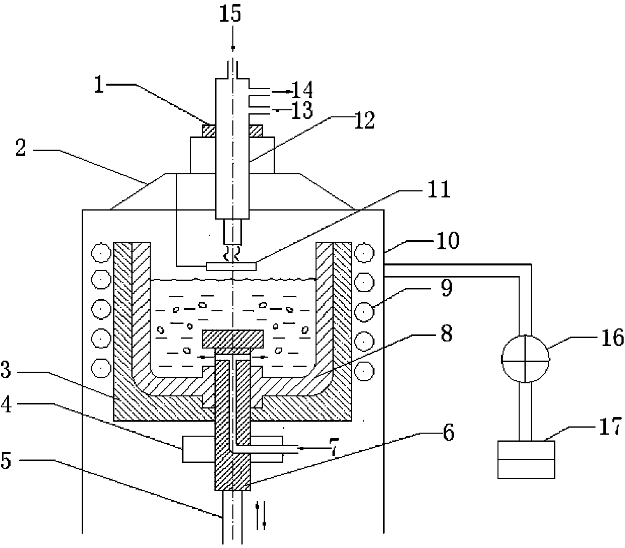
[0049] 2) Put the silicon material into the graphite crucible, start the vacuum system to evacuate, when the vacuum reaches 10Pa, turn on the power supply of the intermediate frequency induction melting furnace, adjust the power to 300kW, and heat the silicon material.

[0050] 3) Increase the power of the medium-frequency induction melting furnace to 350kW to keep the silicon liquid at 1600°C.

[0051] 4) Start the venting plug device and the plasma melting device, feed the mixed gas of argon and water vapor with a volume fraction of 99.5% and 0.5% respectively into the gas pipe of the venting plug, and then raise the venting plug until the gas outlet is far from the bottom of the graphite crucible 10mm. The ventilation rate is 20L / min, the melting time is 45min, and the water vapor content can be controlled by a hygrometer. The pow...

Embodiment 2

[0055] Raw material and technological process are with embodiment 1. Increase the power of the medium-frequency induction melting furnace to 400kW to keep the silicon liquid at 1700°C. A mixed gas of argon and water vapor with a volume fraction of 99% and 1% was passed into the silicon liquid, the gas flow rate was 25L / min, and the melting time was 50min. Pour the silicon liquid into the graphite mold for casting, take out the silicon ingot after standing for cooling, remove 1 / 10 of the head and the tail, and measure the B content in the polysilicon ingot by plasma inductively coupled mass spectrometer (ICP-MS) to be 0.12ppmw, P The content is 0.31ppmw.

Embodiment 3

[0057] Raw material and technological process are with embodiment 1. Increase the power of the medium-frequency induction melting furnace to 450kW to keep the silicon liquid at 1750°C. A mixture of argon and water vapor with a volume fraction of 98.5% and 1.5% was passed into the silicon liquid, the gas flow rate was 30L / min, and the melting time was 60min. Pour the silicon liquid into the graphite mold for casting, take out the silicon ingot after standing for cooling, remove 1 / 10 of the head and tail, and measure the B content in the polysilicon ingot by plasma inductively coupled mass spectrometer (ICP-MS) to be 0.10ppmw, P The content is 0.33ppmw.


PUM


Abstract

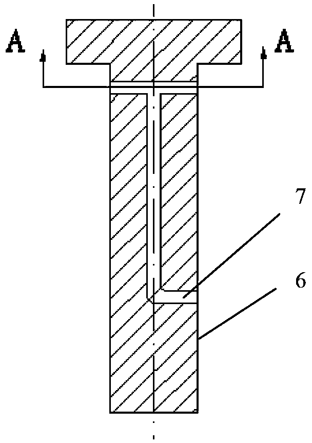
The invention discloses a refining device and method of high purity silicon, and relates to a refining device and method of silicon. The invention provides the refining device and method of high purity silicon, which are low in cost, efficient, simple in process and suitable for industrialized popularization. The device is provided with a medium-frequency induction melting furnace, a lifting device, a plasma melting furnace, a vent plug device, a vacuum system and a graphite die for pouring. The method comprises the following steps: placing a silicon material in a crucible, and starting the melting furnace to heat the silicon material after vacuumizing; improving the power of the melting furnace after the silicon material is melted, and preserving the heat of the silicon liquid at 1600-1850 DEG C; introducing a working gas for melting; starting a melting device, transferring an arc-striking device after striking the arc and carrying out plasma melting on the surface of the silicon liquid; shutting down the melting device after melting, dropping a vent plug to the bottom of the crucible, and shutting down the vent plug device to stop ventilation when the vent plug drops to the bottom of the crucible; and pouring the silicon liquid to the die for pouring to obtain a high purity silicon ingot.

Description

technical field [0001] The invention relates to a silicon refining device and a method thereof, in particular to a high-purity silicon refining device and a method thereof. Background technique [0002] Solar energy is a kind of clean and renewable energy with abundant energy storage. Solar power generation will become an important way to solve energy crisis and environmental problems in the future, and has been widely valued by countries all over the world. With the rapid development of the photovoltaic industry in the world, the waste of electronic grade silicon is far from meeting the requirements, and the technology of chemically purifying polysilicon has hindered solar photovoltaics due to its low yield, high investment cost, pollution and safety. industry development. The metallurgical method is considered to be the most effective technology for reducing the production cost of solar-grade polysilicon because of its short production cycle, low pollution, and low cost, ...

Claims


Application Information

Patent Timeline
Patent Type & Authority Applications(China)
IPC IPC(8): C01B33/037
Inventor 罗学涛黄柳青赖慧先卢成浩方明陈娟李锦堂
Owner XIAMEN UNIV
Learn More