Optically-controlled microwave beam forming networks

A microwave beam and former technology, used in optical fiber transmission, optical fiber radio, wavelength division multiplexing systems, etc., can solve the problems of difficult and effective fast control of beam scanning, slow beam scanning speed, and low delay accuracy. The effect of time error, high practical value, and high delay accuracy

Active Publication Date: 2013-11-27
SHANGHAI INST OF OPTICS & FINE MECHANICS CHINESE ACAD OF SCI
View PDF4 Cites 14 Cited by
  • Summary
  • Abstract
  • Description
  • Claims
  • Application Information

AI Technical Summary

Problems solved by technology

[0005] Traditional beamforming networks using phase shifters have beam tilt effects [see literature [1]Michael Y.Frankel and Ronald D.Esman,True Time-Delay Fiber-optic Control of an ultrawideband Array Transmitted Receiver with Multibeam Capability],, The noise figure of the optical multi-beamformer using a wide-spectrum light source is more than 30dB higher than that of an external modulation link using a single-frequency light source, which seriously affects the signal-to-noise ratio of the system and limits the dynamic range of the system. It is not suitable for transmitting vector signals and other objects. For occasions with high noise requirements (see literature [2] Reconfigurable Optical Beamformer for Simplified Time Steered Arrays, US2002 / 0181874A1, Dec.5, 2002), this system uses a single-frequency light source, and the signal modulation method adopts an external modulation method; The delay network part of the available beamformer mostly adopts the dispersion characteristics of the medium (see literature [3] Photonic dual RF beam reception of an X band phased array antenna using a photonic crystal fiber-based true-time-delay beamformer, Harish subbaraman, Applied Optics, 47, 6448, 2008) and optical switch generation time delay (see literature [2] Reconfigurable Optical Beamformer for Simplified Time Steered Arrays, US2002 / 0181874A1, Dec.5, 2002; literature [4] Optical beam former for high frequency antenna arrays), for time-delay networks using dispersion characteristics, it is difficult to effectively and quickly control beam scanning, beam scanning speed is slow, response speed is slow, delay accuracy is not high, real-time performance is poor, and operability is not strong; due to optical Switches are relatively expensive. For a 4x4 optical beamformer, the number of optical switches that need to be used is 16 to generate different delays, and the delay cannot be continuously adjusted. Using optical switches to form a delay array will result in high costs. The control structure is complicated, and only partial beam scanning can be realized, so the practical value is not high;

Method used


Image

  • Optically-controlled microwave beam forming networks
  • Optically-controlled microwave beam forming networks
  • Optically-controlled microwave beam forming networks

Examples


Embodiment Construction

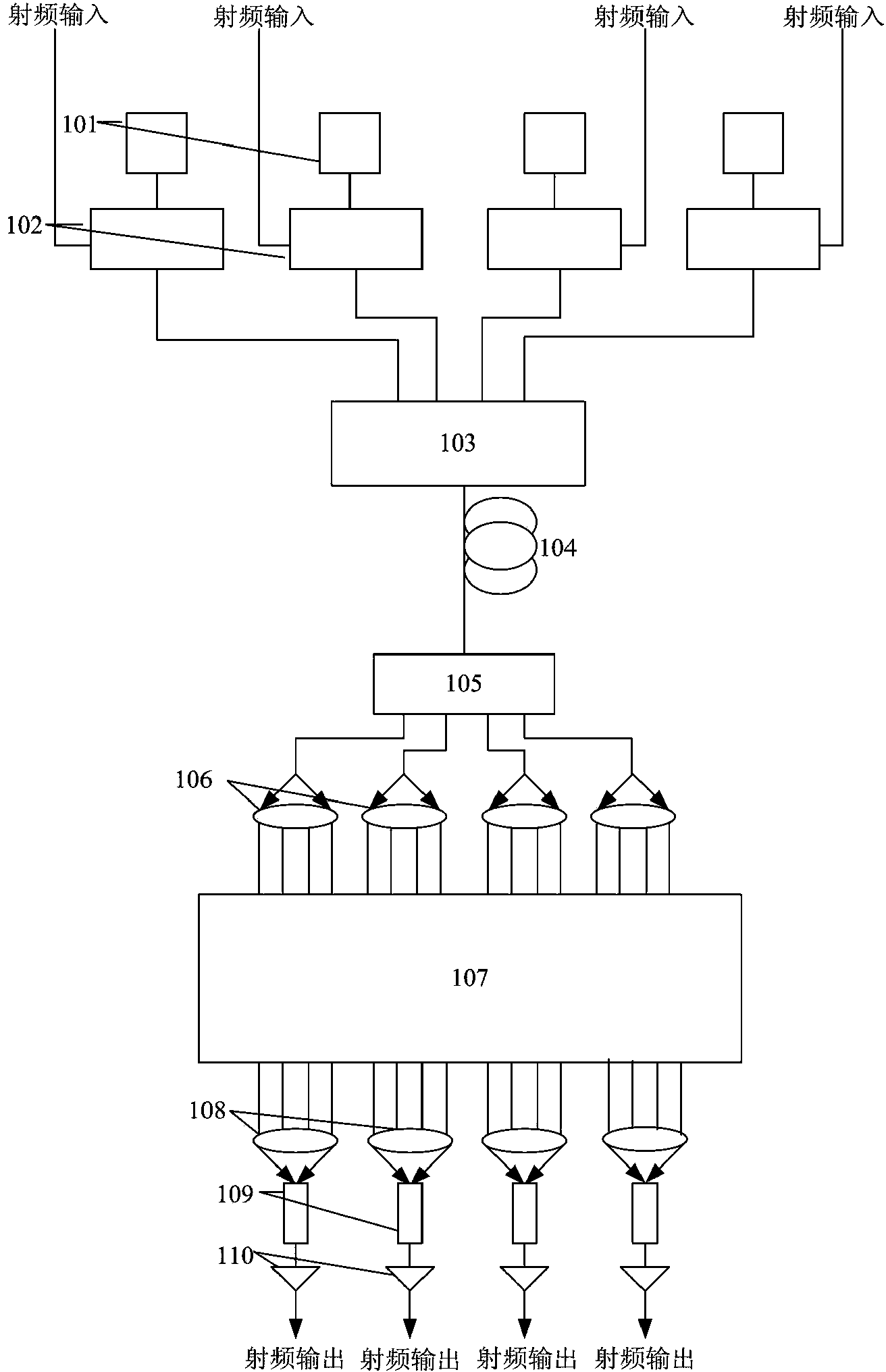
[0020] see first figure 1 , figure 1 It is a block diagram of the structure of the optical beamformer device of the present invention. It can be seen from the figure that the optically controlled microwave beamformer of the present invention comprises 2 N Single-frequency DFB lasers 101, 2 with different wavelengths N An electro-optic intensity modulator 102, 2 N x1 passive wavelength division multiplexer 103, optical fiber 104, 1x2 N Optical beam splitter 105, 2 N A fiber collimator 106, a delay network module 107, 2 N A coupling lens 108, 2 N photodetectors 109 and 2 N A low-noise amplifier 110, wherein n is a positive integer more than 2, and the positional relationship of the above-mentioned components is as follows:

[0021] 2 N The output ends of the single-frequency laser 101 with different wavelengths are respectively connected with 2 N The optical signal input terminals of two electro-optical intensity modulators 102 are connected, and the RF signals capture...


PUM


Abstract

Optically controlled microwave beam forming networks comprise 2N single frequency DFB lasers of different wavelengths, , 2N electro-optic intensity modulators, 2N *1 passive wavelength division multiplexers, an optical fiber, 1*2N optical beam splitter, 2N fiber collimator, a time delay network module, 2N coupled lenses, 2N photoelectric detectors and 2N low noise amplifiers, wherein N is an integer larger than 2. The optically controlled microwave beam forming networks have the advantages of the high signal to noise ratio, good dynamic performance, high time delay precision, continuous adjustability, and good stability, and are easy to be extended in the system array size.

Description

technical field [0001] The invention relates to a broadband optically controlled phased array radar, in particular to an optically controlled microwave beamformer. Background technique [0002] The beamformer (BFN-Beam Forming Networks) is the core of phased array radar and smart antenna. It controls the phase difference or true delay difference of each microwave link in the array to make the radiation field of each microwave radiation source in the far field The specific direction of the interference is extremely large, and the purpose of energy directional emission (or reception) is achieved. Change the phase difference or true delay difference between microwave links to control the direction of the beam. [0003] Beamforming, essentially processing multi-element reception (transmission) to obtain a specific pattern, is the premise and basis for good tactics and performance of modern radar and electronic countermeasure equipment. [0004] The Optically Controlled Microwa...

Claims


Application Information

Patent Timeline
Patent Type & Authority Applications(China)
IPC IPC(8): H04B10/2575H04J14/02H01Q21/00
Inventor 王建蔡海文杨飞王书楠
Owner SHANGHAI INST OF OPTICS & FINE MECHANICS CHINESE ACAD OF SCI
Why Eureka
Try Eureka