Methods for screening and evaluating sperm tropism and dedicated microfluidic control system thereof
A microfluidic chip and tropism technology, applied in biochemical equipment and methods, enzymology/microbiology devices, microbial measurement/inspection, etc., can solve the problem that the impact of fluid shear force on sperm is difficult to avoid
- Summary
- Abstract
- Description
- Claims
- Application Information
AI Technical Summary
Problems solved by technology
Method used
Image
Examples
Embodiment 1
[0060] Embodiment 1, microfluidic chip
[0061] The schematic diagram of the microfluidic chip is shown in figure 1 shown. The microfluidic chip consists of four parts: a sperm inlet pool (3.2 mm in diameter), a main channel (including a 100 μm wide, 500 μm long connecting tube and a 1.5 mm wide, 1.4 mm long gradient forming tube), an outlet pool ( 3.2 mm in diameter), two branch pipes (60 degrees to the main pipe respectively), the size of the branch pipes is suitable for a field of view (830 microns x 630 microns) of the 20× objective lens of the microscope. The dotted line in the figure shows the average swimming distance of sperm from the inlet pool into the branch duct, which is about 4.5 mm. All microchannels are rectangular and 20 microns in height. Two cylindrical microstructures with a diameter of 30 micrometers are arranged at the entrances of the two branch pipes, the distance between the two cylinders is 70 micrometers, and the distance between the cylinder and ...
Embodiment 2
[0063] Example 2, microfluidic chip used in the evaluation of sperm temperature tendency
[0064] First clean the microfluidic tubing with 75% ethanol solution and deionized water respectively, treat the tubing with oxygen plasma, and fill it with 5% CO 2 , Human fallopian tube fluid (HTF) was incubated overnight at 37°C, and the inlet pool was covered with mineral oil to prevent volatilization.
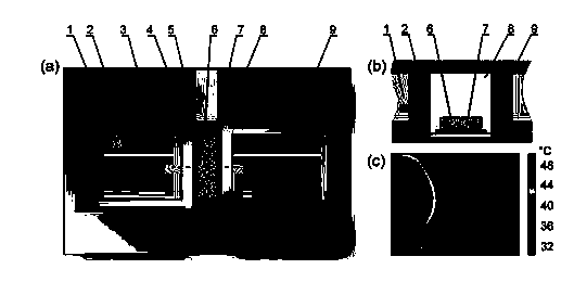
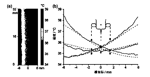
[0065] Then the microfluidic chip of Example 1 is inserted as figure 2 The temperature gradient control device shown. The position where the chip is placed is the chip placement cavity 8, and the positive pressure in the outlet pool is passed into the air at a flow rate of 2 ml / hour, so that the gas-liquid interface enters the pipeline, reaching Figure 5 (c) The position shown. The part of the chip with microfluidic channels is completely surrounded by air and does not come into contact with other liquids or solids. The left and right sides of the chip placement cavity 8 are re...
Embodiment 3
[0070] Example 3, microfluidic chips are used for the capture of sperm with different motility
[0071] From the outlet pool, continue to feed air at a flow rate of 2 ml / hour to push the interface between the air and HTF towards the inlet pool. The process is as follows: Figure 5 As shown in (c)-(e), two approximately flat gas-liquid interfaces are finally formed at the entrances of the two branch pipes to prevent the exchange between the sperm in the main pipe and the sperm in the branch pipes to complete the swimming Capture of sperm by two branching ducts. The final capture effect is as follows figure 1 The magnification of the dashed area in the center is shown. Because the connecting pipe part of the main pipe is very thin, the gas-liquid interface cannot pass through the connecting pipe at a flow rate of 2 ml / hour, and a gas-liquid interface is also formed at the junction of the connecting pipe and the gradient forming pipe, such as Figure 5 (e) shown.
PUM
 Abstract
Description
Claims
Application Information
 - R&D
- Intellectual Property
- Life Sciences
- Materials
- Tech Scout
- Unparalleled Data Quality
- Higher Quality Content
- 60% Fewer Hallucinations
Browse by: Latest US Patents, China's latest patents, Technical Efficacy Thesaurus, Application Domain, Technology Topic, Popular Technical Reports.
© 2025 PatSnap. All rights reserved.Legal|Privacy policy|Modern Slavery Act Transparency Statement|Sitemap|About US| Contact US: help@patsnap.com


