Sputtering method for sull
A technology of oxide thin film and thin film, which is applied in the direction of sputtering plating, ion implantation plating, metal material coating technology, etc., can solve the problems of poor withstand voltage characteristics and insufficient density of the film, and achieve large process window and high pressure resistance. Good effect
- Summary
- Abstract
- Description
- Claims
- Application Information
AI Technical Summary
Problems solved by technology
Method used
Image

Examples
Embodiment 1
[0027] The invention relates to a sputtering method of an oxide thin film, which is to directly feed ozone into a reaction chamber of a physical vapor deposition device as a sputtering gas to deposit an oxide thin film. Preferably, the flow rate of ozone introduced into the reaction chamber accounts for 0.1%-50% of the total flow rate of the gas used for sputtering. Preferably, the flow rate of ozone introduced into the reaction chamber accounts for 5% or 10% or 30% or 40% of the total flow rate of the gas used for sputtering.
[0028] The physical vapor deposition equipment can be any one of DC sputtering, radio frequency sputtering, intermediate frequency sputtering, AC sputtering or pulsed DC sputtering equipment. The physical vapor deposition equipment can be a single-target direct sputtering method or a multi-target co-sputtering method.
[0029] The sputtering method of the oxide thin film of the present invention is to directly introduce ozone into the reaction chamber...
Embodiment 2
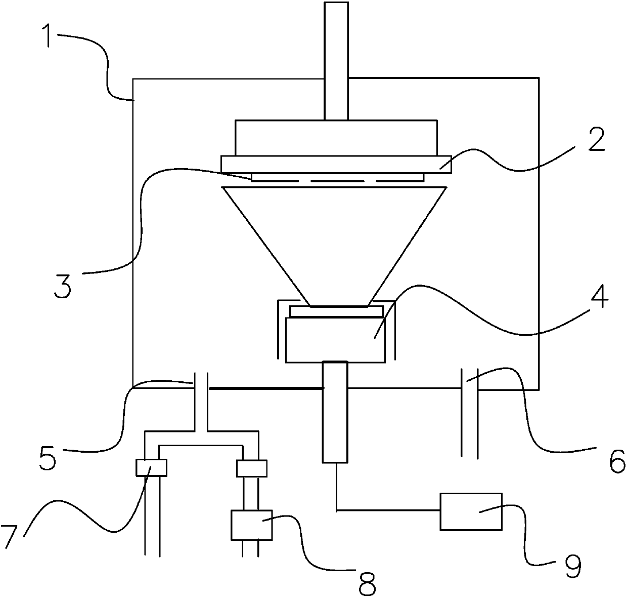
[0037] The indium zinc gallium oxide ceramic target is used as the sputtering target 4, and figure 1 The shown physical vapor deposition equipment prepares oxide semiconductor films with low oxygen vacancies by radio frequency magnetron sputtering.
[0038] Its concrete preparation steps are as follows:
[0039] (1) Vacuum the sputtering reaction chamber 1 to a pressure of 10 -4 Below Pa;
[0040] (2) Passing in the substrate glass substrate 3 by the robot arm;
[0041] (3) Charge Ar, turn on the ozone generator 8, adjust the flow rate of the charged gas through the flow controller 7, so that the flow ratio of the ozone in the reaction chamber 1 to the total sputtering gas is 5%, and control the total sputtering gas The pressure is 5mTorr; Among them, the ozone generator generates ozone by means of corona discharge.
[0042] (4) After the air pressure in the sputtering chamber is stabilized, turn on the RF power supply 9 and set the power of the device to 500 W;
[0043]...
Embodiment 3
[0047] The indium zinc oxide ceramic target is used as the sputtering target 4, such as figure 1 The shown physical vapor deposition equipment uses DC magnetron sputtering to prepare oxide semiconductor thin films with low oxygen vacancies.
[0048] Its concrete preparation steps are as follows:
[0049] (1) Vacuum the sputtering reaction chamber 1 until the vacuum degree reaches 10-4 Below Pa;
[0050] (2) Pass in the flexible PI substrate 3 with glass as the carrier through the robot arm;
[0051] (3) Fill in Ar, turn on the ozone generator 8 to generate ozone by ultraviolet irradiation, adjust the flow rate of the charged gas through the flow controller 7, so that the flow ratio of ozone and total sputtering gas is 5%, and control the total sputtering The gas pressure is 5mTorr;
[0052] (4) After the air pressure in the sputtering chamber is stable, turn on the RF power supply 9 and set the power to 500 W;
[0053] (5) By controlling the sputtering time, a 100nm indiu...
PUM
| Property | Measurement | Unit |
|---|---|---|
| breakdown field strength | aaaaa | aaaaa |
| breakdown field strength | aaaaa | aaaaa |
| relative permittivity | aaaaa | aaaaa |
Abstract
Description
Claims
Application Information
 - R&D
- Intellectual Property
- Life Sciences
- Materials
- Tech Scout
- Unparalleled Data Quality
- Higher Quality Content
- 60% Fewer Hallucinations
Browse by: Latest US Patents, China's latest patents, Technical Efficacy Thesaurus, Application Domain, Technology Topic, Popular Technical Reports.
© 2025 PatSnap. All rights reserved.Legal|Privacy policy|Modern Slavery Act Transparency Statement|Sitemap|About US| Contact US: help@patsnap.com