
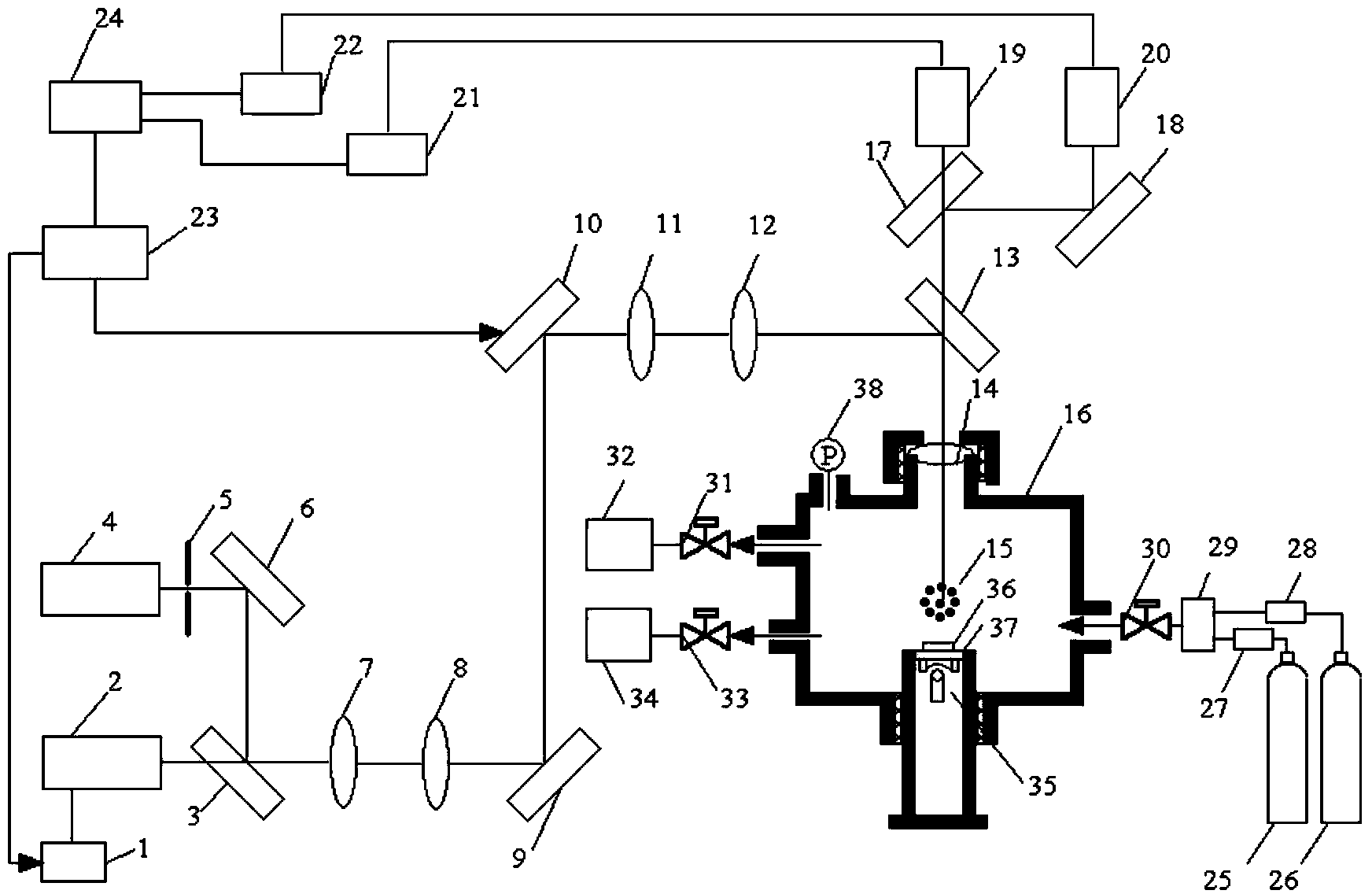
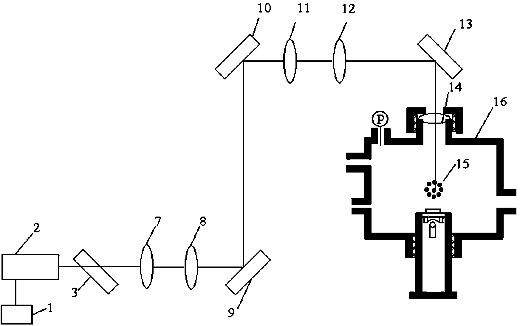
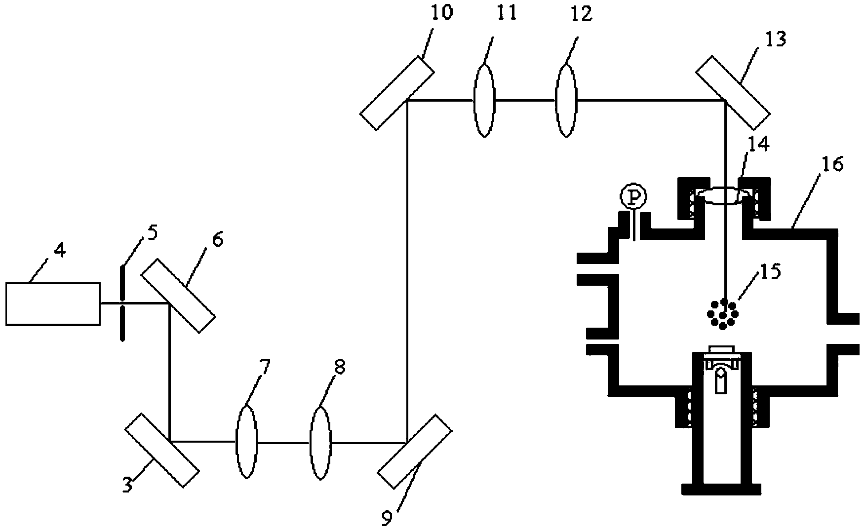
Microparticle swarm fuel micro-combustion system based on digital holographic optical tweezers

A digital holographic and micro-particle technology, applied in the direction of burners, combustion methods, combustion types, etc., can solve the problems of shortened residence time, reduced combustion efficiency, and increased influence of the overall reaction, so as to improve the composition mode and increase the combustion efficiency. Effect

Active Publication Date: 2013-12-18
HANGZHOU DIANZI UNIV
View PDF4 Cites 10 Cited by
  • Summary
  • Abstract
  • Description
  • Claims
  • Application Information

AI Technical Summary

Problems solved by technology

(2) Smaller fuel residence time: With the reduction of the scale, the residence time of the fuel in the combustion chamber is greatly reduced, usually about 0.5ms, which reaches the characteristic reaction time of the fuel, so the Dunkel's quasi-number Da is close to Even less than 1, so a lot of fuel is excluded from the outside before it can react, and the combustion efficiency is reduced
(3) Large combustion heat loss: As the scale decreases, the surface area to volume ratio of the combustion chamber increases greatly, and the corresponding surface heat dissipation also increases greatly, thus affecting the combustion efficiency
On a large scale, the wall surface consumption of free radicals can be ignored, but on a microscale, the distance for molecules to diffuse to the wall surface is very short, and the collision frequency with the wall surface per unit time increases, so the wall surface consumption of free radicals is very large, which has a greater impact on the overall reaction

Method used


Image

  • Microparticle swarm fuel micro-combustion system based on digital holographic optical tweezers
  • Microparticle swarm fuel micro-combustion system based on digital holographic optical tweezers
  • Microparticle swarm fuel micro-combustion system based on digital holographic optical tweezers

Examples


Embodiment Construction

[0022] The present invention will be further described below in conjunction with accompanying drawing.

[0023] Classical holographic technology uses the interference principle of light to record the light wave front emitted by the object in the form of interference fringes to achieve the purpose of freezing the phase information of the light wave of the object; using the diffraction principle of light to reproduce the wave front of the recorded object light wave, we can get The amplitude (intensity) and phase (including position, shape and color) information of an object has unique advantages in the field of optical detection and three-dimensional imaging.

[0024] Digital holography refers to the use of CCD imaging devices instead of ordinary photographic coherent plates to record holograms and reproduce them with digital computing methods; later, the scope of digital holography was expanded to computer-made holograms, photoelectron reproduction holograms, etc., forming a bro...


PUM


Abstract

The invention relates to a microparticle swarm fuel micro-combustion system based on digital holographic optical tweezers. The system comprises a first laser driver, a first laser, a first spectroscope, a second laser, an attenuation slice, a second reflection lens, a collimating lens group, a first reflection lens, a spatial light modulator, a beam-expanding lens group, a second spectroscope, an objective lens, a microparticle swarm fuel, a micro-combustion chip, a third spectroscope, a third reflection lens, a CCD (Charge Coupled Device) camera, an infrared camera, a first image acquisition card, a second image acquisition card, a data acquisition card, a computer, a nitrogen storage bottle, an oxygen storage bottle, a first flowmeter, a second flowmeter, a buffering tank, a first valve, a second valve and a gas chromatograph-mass spectrometer. The distribution pattern of the fuel can be effectively controlled through a digital holographic technology and the spatial light modulator, so that the combustion of the microparticle swarm fuel can be performed in the micro-combustion chip; the composition mode of the micro-combustion can be effectively improved; the combustion efficiency of the micro-combustion is improved.

Description

technical field [0001] The invention belongs to the technical field of micro-combustion, and relates to a micro-particle group fuel micro-combustion system based on digital holographic optical tweezers. Background technique [0002] The function of micro-combustion is the same as that of traditional combustion, which is to efficiently convert the chemical energy of fuel into thermal energy and kinetic energy, and at the same time, it has a reliable ignition method, a wide operating limit and a small pressure loss. However, the reduction in scale brings many challenges to microscale combustion: (1) Fuel mixing is difficult: because the Reynolds number of microscale small fuel mixture flow is small, the flow is in a laminar state. Mixing therefore cannot rely on intense turbulent mixing, but on molecular diffusion. (2) Smaller fuel residence time: With the reduction of the scale, the residence time of the fuel in the combustion chamber is greatly reduced, usually about 0.5ms,...

Claims


Application Information

Patent Timeline
IPC IPC(8): G01N21/84G01N30/88F23D99/00
Inventor 李盛姬黄雪峰
Owner HANGZHOU DIANZI UNIV
Learn More