Improved Manufacturing Method of Solid Electrolytic Capacitor
A solid-state electrolysis and capacitor technology, applied in the direction of solid electrolytic capacitors, electrolytic capacitors, capacitors, etc., can solve the problems of difficult manufacturing process and assembly, complex process, high short-circuit rate, etc., to improve yield, reduce process time, and simplify complexity. Effect
- Summary
- Abstract
- Description
- Claims
- Application Information
AI Technical Summary
Problems solved by technology
Method used
Image
Examples
no. 1 example 〕
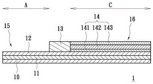
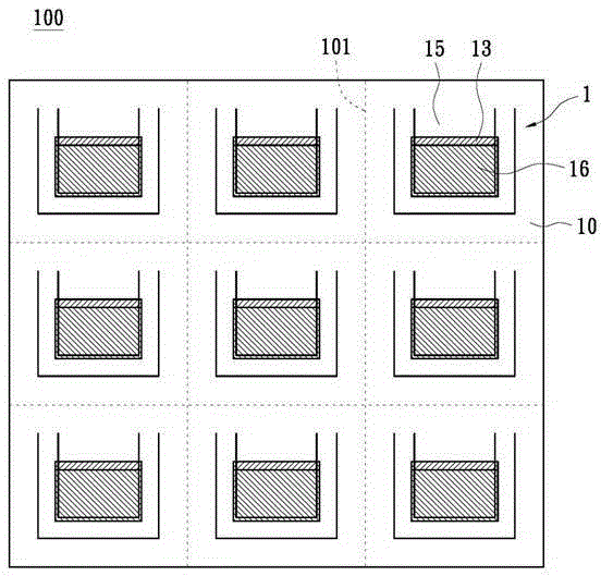
[0048] see figure 1 , which shows the schematic flow chart of the improved manufacturing method of the solid electrolytic capacitor of the first embodiment of the present invention; and refer to figure 2 and 3 , the specific features of each step will be described in detail below.
[0049] Step 1: providing an insulating substrate 10 . The insulating substrate 10 is made of aluminum oxide (Al 2 o 3 ) substrate is most suitable.
[0050] Step 2: forming a conductive colloid containing aluminum powder (not shown). The conductive gel contains 0 to 50 weight percent of thermosetting resin, 30 to 100 weight percent of aluminum powder and 0 to 50 weight percent of curing agent. Specifically, epoxy resin is the most suitable thermosetting resin, but it is not limited thereto; moreover, in order to have better conductivity, the particle size of aluminum powder should be between 0.05 and 5 microns, and the surface of aluminum powder should It can be pre-treated to form a concav...
no. 2 example
[0063] see Figure 4 , which shows a schematic flow chart of the improved manufacturing method of the solid electrolytic capacitor according to the second embodiment of the present invention; and please cooperate Figure 5 , the specific features of each step will be described in detail below.
[0064] Step 1: Provide aluminum powder. A binder, such as camphor, stearic acid, polyvinyl alcohol, naphthalene, etc., can also be added to the aluminum powder, and the amount of the binder is roughly 3 to 5 wt%.
[0065] Step 2, forming an aluminum ingot; specifically, after fully mixing the above-mentioned aluminum powder and a binder, a cold pressing process is performed, and the aluminum powder is pressed into a rectangular aluminum ingot 21 by using a die; preferably Ground, the load during cold pressing is 3 to 15MN (MegaNewton) / m 2 , so that the cold-pressed aluminum ingot 21 has a better bulk density. Moreover, in the above-mentioned cold pressing process, it further includ...
no. 3 example
[0073] see Figure 6 , which shows the schematic flow chart of the improved manufacturing method of the solid electrolytic capacitor of the third embodiment of the present invention; and please cooperate Figure 7 , the specific features of each step will be described in detail below.
[0074] Step 1: making anode foil 31 and cathode foil 32 . Specifically, the anode foil 31 is made by first spraying aluminum powder on the sheet-shaped aluminum foil, and then performing a high-temperature sintering procedure after drying to form an aluminum porous high-temperature sintered body, and then forming an oxide film on the surface of the high-temperature sintered body ; The temperature range and time of the high-temperature sintering process can refer to the first embodiment, so it will not be repeated here; in a variation embodiment, titanium and / or hydrides can also be selectively added to the aluminum powder for sintering additives to become aluminum mixed raw material powder. ...
PUM
| Property | Measurement | Unit |
|---|---|---|
| particle diameter | aaaaa | aaaaa |
| thickness | aaaaa | aaaaa |
| thickness | aaaaa | aaaaa |
Abstract
Description
Claims
Application Information
 - R&D
- Intellectual Property
- Life Sciences
- Materials
- Tech Scout
- Unparalleled Data Quality
- Higher Quality Content
- 60% Fewer Hallucinations
Browse by: Latest US Patents, China's latest patents, Technical Efficacy Thesaurus, Application Domain, Technology Topic, Popular Technical Reports.
© 2025 PatSnap. All rights reserved.Legal|Privacy policy|Modern Slavery Act Transparency Statement|Sitemap|About US| Contact US: help@patsnap.com


