Tank-surface-evaporation solar thermal power generation system

A solar thermal power generation and evaporation pond technology, which is applied in the directions of solar thermal power generation, mechanical power generation with solar energy, steam engine installations, etc. Easy to be damaged and other problems, to achieve the effect of saving metal consumables, large evaporation, and fast evaporation rate

Inactive Publication Date: 2013-12-25
JIMEI UNIV
View PDF5 Cites 4 Cited by
  • Summary
  • Abstract
  • Description
  • Claims
  • Application Information

AI Technical Summary

Problems solved by technology

The overall efficiency of the concentrating thermal power generation system is high, but the system structure is complex and the production cost is expensive. Except for the trough power station that has entered the commercialization stage, the other two are still in the research and experimental stage; the solar pool power generation system has a simple structure and low construction cost. Low cost and low power generation cost. It is the cheapest and most popular technology among all solar energy applications. However, there are still some shortcomings: 1. The salt gradient in the pool is easily destroyed, and a large amount of salt needs to be replenished periodically, which increases the Operating costs and power generation costs. The second is that the evaporator and condenser in the power generation equipment have poor heat transfer ends, resulting in a decrease in power generation efficiency; the solar chimney thermal airflow power generation system is conducive to improving and rebuilding the ecological environment, but the efficiency is very low

Method used


Image

  • Tank-surface-evaporation solar thermal power generation system

Examples


Embodiment Construction

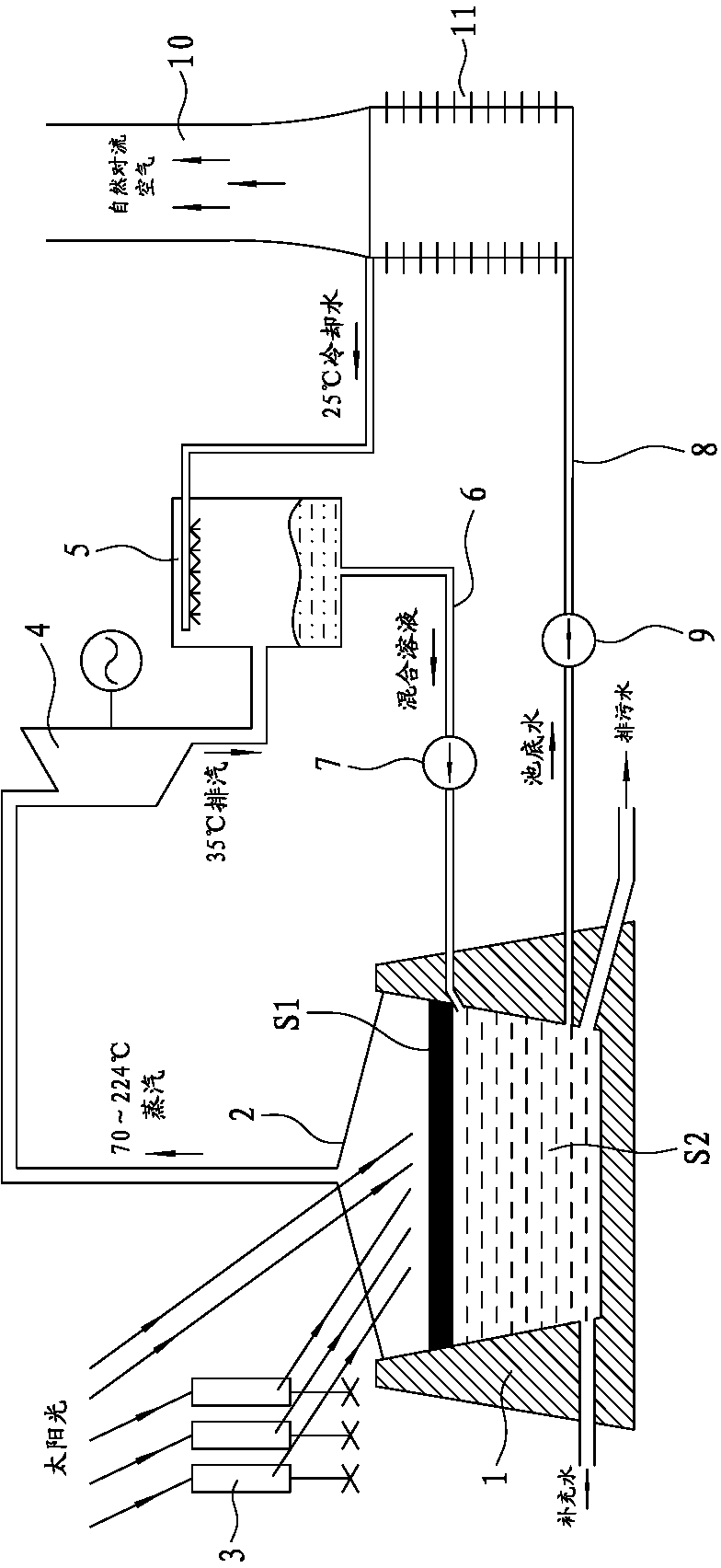
[0014] Such as figure 1 As shown, the present invention is a pool surface evaporation type solar thermal power generation system, which includes an evaporation pool 1, a light-transmitting ceiling 2, a mirror array 3, a turbogenerator set 4, a hybrid condenser 5, and a mixed solution pipeline 6 , Solution pump 7, cooling water pipeline 8, cooling water pump 9, cooling tower 10, air cooler 11.

[0015] The evaporation pool 1 is a natural freshwater lake or an artificial deep water pool added with a low-boiling point refrigerant, and its depth is between 20 and 200m; the liquid in the evaporation pool 1 is divided into upper and lower layers, and the upper layer is a low-boiling point refrigerant with a certain thickness. Layer S1, the lower layer is the freshwater layer S2. The thickness of the low-boiling point working fluid layer S1 is between 0.3 and 2m, and the low-boiling point organic working fluid is selected as a working medium that is insoluble or hardly soluble in wa...


PUM


Abstract

The invention discloses a tank-surface-evaporation solar thermal power generation system comprising an evaporation tank, a light-permeable ceiling, a mirror array, a steam turbine generator set, a hybrid condenser, a mixed solution pipeline, a solution pump, a cooling water pipeline, a cooling water pump, a cooling column, and an air cooler. Liquid in the evaporation tank is composed of low-boiling-point medium layer and a fresh water layer; radiant energy of sunlight is transmitted to the low-boiling-point medium layer by means of direct irradiation and reflection; obtained high-pressure steam dives the steam turbine generator set to act to generate power; cooling water led from the bed of the evaporation tank dissipates heat through the cooling column, enters the hybrid condenser and contacts and condenses to discharged so that mixed solution is formed; the mixed solution is delivered back into the evaporation tank by the solution pump; the low-boiling-point medium and the fresh water are unable to dissolve due to density difference and automatically layer. The tank-surface-evaporation solar thermal power generation system is simple in structure, high in heat collection efficiency, high in energy conversion rate, high in circulating efficiency, high in station capacity, low in building cost, suitable for low-cost large-scale production, and widely applicable to the technical field of solar thermal power generation technologies.

Description

technical field [0001] The invention belongs to the technical field of solar thermal power generation, in particular to a pool surface evaporation type solar thermal power generation system. Background technique [0002] In the current situation that countries around the world are facing increasing energy shortages, people have taken solar energy as one of the main modern new energy sources for development and utilization. Therefore, obtaining energy from the sun, the inexhaustible energy treasure house, to realize the energy transformation in human history has become the main trend of energy development in the future, and solar power generation should be the main force to provide large-scale power in the future. At present, my country's solar photovoltaic industry has begun to rise, while the research and application of solar thermal power generation is still relatively backward. The large-scale characteristics of solar thermal power generation determine that its huge poten...

Claims


Application Information

Patent Timeline
Patent Type & Authority Applications(China)
IPC IPC(8): F03G6/00F01K25/08F01K9/00
CPCY02E10/46
Inventor 陈志强何宏舟蒋俊尧蔡佳莹林思洋赵光慧林芳
Owner JIMEI UNIV
Why Eureka
Try Eureka