Small microbial electrolysis cell and application thereof

A microbial electrolytic cell, small-scale technology, applied in the field of water treatment, can solve problems such as difficulty in finding aeration devices, influence of experimental results, uneven aeration, etc., and achieve good experimental results, simple structure, and convenient use

Inactive Publication Date: 2014-03-12
SHANDONG UNIV
View PDF4 Cites 4 Cited by
  • Summary
  • Abstract
  • Description
  • Claims
  • Application Information

AI Technical Summary

Problems solved by technology

However, existing microbial electrolytic cells have obvious deficiencies when simulating natural water body experiments in real environments. At the same time, there is often uneven aeration for small microbial electrolytic cells, and it is not easy to find suitable aeration devices. In addition, the stirrer in the existing microbial electrolytic cell is likely to cause the electrode to shake in the electrolyte when it is stirred, which will affect the experimental results

Method used


Image

  • Small microbial electrolysis cell and application thereof
  • Small microbial electrolysis cell and application thereof
  • Small microbial electrolysis cell and application thereof

Examples


Embodiment 1

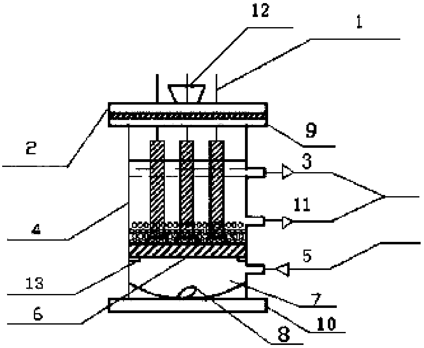
[0035] Such as figure 1 , figure 2Shown, a kind of small-scale microbial electrolytic cell, the structure of this electrolytic cell comprises flange 2, electrode 1, copper rod, microbial electrolytic cell reactor 4, aeration plate 6 and ion stirrer 8, wherein, microbial electrolytic cell reactor 4 is a hollow cylindrical container, the bottom edge of the cylindrical container is set as an outwardly extending base 10, the top of the cylindrical container is open, and the edge of the opening is set as an outwardly extending boss 9, and the flange 2 is passed through the bolt It is fixedly connected with the boss 9, and the center of the flange 2 is provided with a through hole, and a circle of electrode holes penetrating the flange is arranged outside the through hole, and the electrodes include 3 polyaniline graphite electrodes and 3 ordinary graphite electrodes, and the polyaniline graphite electrodes are Negative electrode, ordinary graphite electrode is positive electrode,...

Embodiment 2

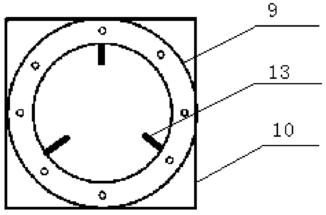
[0037] Such as figure 1 , image 3 with Figure 4 Shown, a kind of small-sized microbial electrolytic cell, its structure is as shown in embodiment 1, and difference is: the bottom of cylindrical container is equipped with stirring tank 7, and stirring tank 7 is the arc-shaped container that the center portion is sunken downwards. The advantage of this design is that the stirrer 8 can be placed in the stirring tank 7, which relatively increases the thickness of the bottom of the reactor of the microbial electrolytic cell, and avoids the damage of the bottom of the reactor caused by the stirring of the stirrer 8 for a long time.

Embodiment 3

[0039] Such as figure 1 with figure 2 Shown, a kind of small-scale microbial electrolytic cell, its structure is as shown in embodiment 2, difference is: the diameter of the electrode hole on the flange 2 is 0.5mm.


PUM

PropertyMeasurementUnit
diameteraaaaaaaaaa

Abstract

The invention relates to a small microbial electrolysis cell and application thereof. The electrolysis cell includes a flange, electrodes, copper bars, a microbial electrolysis cell reactor, an aeration plate and a stirring bar. Tiny aeration holes are uniformly formed in the aeration plate to allow gas bubbles to uniformly enter an electrolyte during N2 charging, so that the phenomenon that sudden gas expansion during N2 charging leads to unstable aeration, corrosion of the copper bars by the solution, and influence on the experiment effect is avoided. The electrodes are inserted into electrode clamping grooves in the upper surface of the aeration plate, electrons are supplied by an external electric field, and a DO or pH probe regularly passes through a through hole in the flange and fixed in a probe clamping groove in the center of the aeration plate, so that the DO or pH value of a reaction system can be monitored in real time. The microbial electrolysis cell can achieve stable and efficient degradation of perchlorate in water bodies.

Description

technical field [0001] The invention relates to a small microbial electrolytic cell and its application, belonging to the technical field of water treatment. Background technique [0002] In recent years, perchlorate has been detected in a large amount of water, soil and food, which has attracted great attention from people all over the world. Since perchlorate ingestion into the human body will lead to insufficient secretion of thyroid hormones, thereby inhibiting the normal metabolism and growth of the human body, therefore, finding an effective way to eliminate such pollutants has become one of the major environmental issues concerned by the world. Microbial degradation is the most important way to remove perchlorate pollution in the environment. Anaerobic microorganisms are used to degrade perchlorate into non-toxic and harmless chlorides under anaerobic conditions, and microbial degradation is the most economical, convenient, and non-toxic. An effective method of secon...

Claims


Application Information

Patent Timeline
Patent Type & Authority Applications(China)
IPC IPC(8): H01M8/16H01M8/02H01M8/0202
CPCY02E60/527C02F3/28C02F3/34H01M8/02H01M8/16Y02E60/50
Inventor 高明明李佳佳
Owner SHANDONG UNIV
Why Eureka
Try Eureka