Tail gas catalysis combustion treatment system

A catalytic combustion and treatment system technology, applied in chemical instruments and methods, dispersed particle separation, separation methods, etc., can solve the problems of inability to drive, large incineration exhaust, high operating costs, etc., to prolong the service life and fully respond Exhaust heat, exhaust gas treatment thorough effect

Inactive Publication Date: 2014-03-26
上海凯鸿环保工程有限公司
View PDF5 Cites 19 Cited by
  • Summary
  • Abstract
  • Description
  • Claims
  • Application Information

AI Technical Summary

Problems solved by technology

Due to the low concentration of organic matter and high toxicity in the tail gas of the absorption tower of the acrylonitrile plant, the general tail gas treatment process cannot meet the environmental protection requirements. At present, the tail gas of the absorption tower of the acrylonitrile plant is generally discharged directly from the high point of the chimney, causing serious pollution to the environment.
[0003] In addition, some acrylonitrile plants use thermal incineration to treat acrylonitrile tail gas, but the disadvantage of thermal incineration is that it consumes a large amount of fuel, the operating cost is high, and the incineration exhaust gas is large, and a small amount of NOx will be produced during the incineration process.
[0004] Furthermore, in the prior art, there has been a concept of catalytic oxidation treatment of acrylonitrile tail gas, but the catalytic oxidation treatment process is a very complicated treatment process. Although there is a theoretical concept of treatment at present, there is no successful treatment in practice. The case experience can be used as a reference. Often the system is built, but it cannot be driven and operated at all, let alone the treatment of acrylonitrile tail gas. Therefore, the current treatment method is still mainly thermal incineration.

Method used


Image

  • Tail gas catalysis combustion treatment system

Examples


Embodiment approach

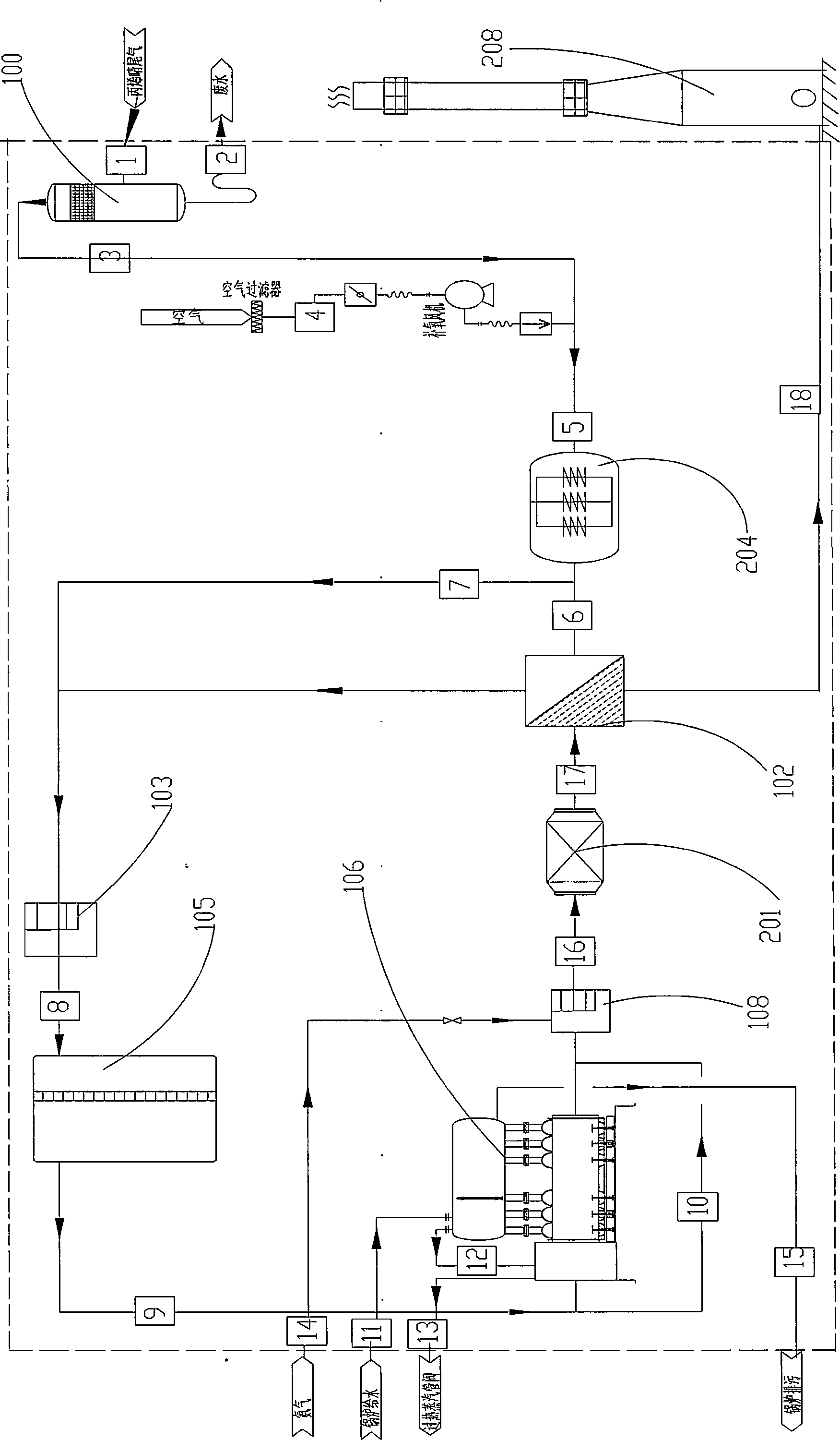
[0025] Such as figure 1 As shown, the tail gas catalytic combustion treatment system of the present invention at least includes:

[0026] Condenser 100 is a condenser for preliminary filtration and condensation of the acrylonitrile tail gas discharged from the production line. The condensed gas is mixed with the air in the pipeline 4 through the pipeline 3 and then enters the heater 5. The condensed condensate includes waste water through the Line 2 exits.

[0027] Furnace start-up circulation pipeline 101, which includes pipelines 1-17 and valves located on the above-mentioned pipelines, can be used for closed furnace start-up, which can effectively reduce the consumption of electric and heat energy when starting the furnace, and save energy.

[0028] The plate heat exchanger 102, or heat exchanger, adopts countercurrent convection, has good heat exchange effect and saves energy, and it is equipped with a bypass line 7, which is designed according to the final start-up tempe...


PUM


Abstract

The present invention provides a tail gas catalysis combustion treatment system, which at least comprises: a heater for heating tail gas and air, a CO reactor for carrying out a catalysis oxidation reaction on the heated air and heated tail gas mixed gas, a SCR reactor for carrying out a further catalysis reduction reaction on the gas discharged from the CO reactor after the catalysis oxidation reaction, a heat exchanger for carrying out heat recovery on the gas discharged from the SCR reactor after the catalysis reduction reaction and carrying out heat exchange heating on the air and tail gas mixed gas entering the CO reactor, and a chimney for outward discharging the gas discharged after heat exchange. The tail gas catalysis combustion treatment system has characteristics of simple process, circuitous equipment arrangement, small occupation area, good reasonability, conversion of harmful volatile organic compounds in the tail gas into carbon dioxide and water, no secondary pollution, and complete tail gas treatment, wherein the detection result completely meets the environmental protection control requirements of the country.

Description

technical field [0001] The invention relates to a tail gas catalytic combustion treatment system, in particular to a catalytic combustion treatment system for absorption tower tail gas in the process of producing acrylonitrile. Background technique [0002] The acrylonitrile plant using propylene ammoxidation technology uses propylene, ammonia, and air as the main raw materials. Under the action of a catalyst, it reacts to produce acrylonitrile and other by-products, and then undergoes processes such as quenching, recycling, and refining to obtain acrylonitrile products. In the production process of acrylonitrile, a stream of gas is discharged from the top of the absorption tower, which is called the absorption tower off-gas (AOG). The main components of the tail gas are nitrogen, water vapor and carbon dioxide, and also contain a certain amount of carbon monoxide, acrylonitrile, propylene and propane and other harmful components that pollute the environment. Due to the low...

Claims


Application Information

Patent Timeline
Patent Type & Authority Applications(China)
IPC IPC(8): B01D53/86B01D53/90B01D53/72B01D53/62B01D53/56
Inventor 刘永隆林家泰林蔚丞
Owner 上海凯鸿环保工程有限公司
Why Eureka
Try Eureka