Implementing method of high-voltage square-wave generator

A square wave generator and realization method technology, applied in the field of power system, can solve the problems of being susceptible to surrounding electromagnetic interference, limited withstand voltage of mercury-wetting switches, short output pulse width, etc. The effect of strong electromagnetic interference ability and strong load capacity

Active Publication Date: 2014-03-26
STATE GRID CORP OF CHINA +3
View PDF4 Cites 13 Cited by
  • Summary
  • Abstract
  • Description
  • Claims
  • Application Information

AI Technical Summary

Problems solved by technology

[0003] The square wave generator based on the mercury switch is usually used. The advantages of this type of generator are: easy to use, good repetition frequency characteristics, and the rise time of the square wave can reach ns level, which can meet the requirements of the step wave response test, but Mercury switches have limited withstand voltage, and ordinary mercury switches can only generate (100-300) V low-voltage square waves
With the increase of the voltage level, the voltage division ratio of the impact voltage divider continues to increase. When the low-voltage square wave signal is applied to the high-voltage side of the voltage divider, the signal measured on the low-voltage side is quite weak, and it is susceptible to surrounding electromagnetic interference. It cannot be distinguished on the measurement digital oscilloscope, let alone analysis and calculation
In addition, for a pulse generator that uses a pulse forming line or a Marx circuit and is designed based on the steepening switch principle, although the rise time of the output square wave can be very short (several ns or even ps level), and the amplitude can also reach Tens of kilovolts, but its output pulse width is very short, usually only a few hundred ns, and the jitter is large
Since the stabilization time of the impact resistance voltage divider is generally about 200ns, the stabilization time of the weak damping voltage divider is longer, so the exact stabilization

Method used


Image

  • Implementing method of high-voltage square-wave generator
  • Implementing method of high-voltage square-wave generator

Examples


Embodiment

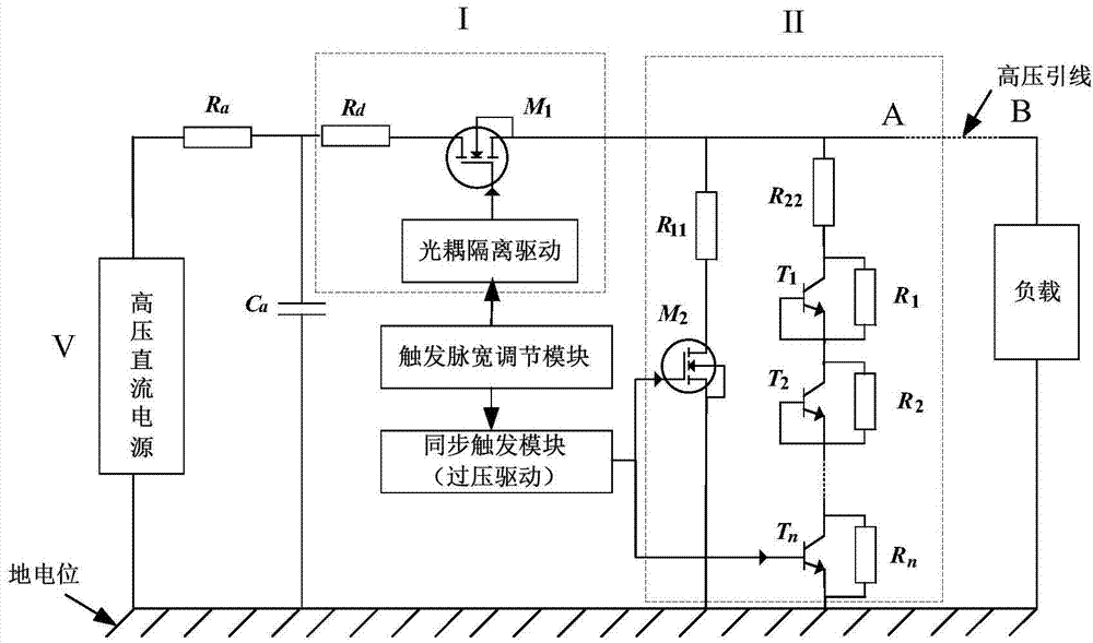
[0036] figure 1 The tag description in is:

[0037] V—DC power supply, R a — DC charging resistance, C a — energy storage capacitor, R d —Current limiting damping resistor, I—rising edge circuit, II—falling edge circuit, M 1 — Front MOSFET, M 2 — Rear stage MOSFET, T 1 , T 2 , T 3 ...T n — avalanche triode, R 1 , R 2 , R 3 ...R n — grading resistance, R 11 , R 22 — Damping resistance, point A is the output end of the square wave generator, point B is the high voltage end of the load, and section AB is the high voltage lead.

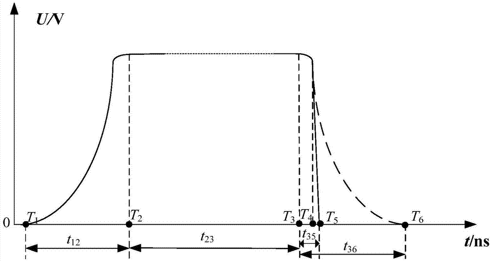
[0038] figure 2 The tag description in is:

[0039] T 1 —Triggering time of front MOSFET; T 2 —The moment when the front-stage MOSFET is fully turned on; T 3 —The triggering time of the rear-stage MOSFET; T 4 —Avalanche triode trigger time; T 5 —The moment when the avalanche transistor is fully turned on; T 6 —The moment when the rear-stage MOSFET is fully turned on; t 12 —Rising edge time of square wave voltage; t 23 —Square wave...


PUM


Abstract

The invention relates to an implementing method of a high-voltage square-wave generator. The generator comprises a high-voltage DC (Direct Current) source, a resistor, an energy storage capacitor, a triggering pulse width adjusting module, a rising edge circuit, a falling edge circuit and a synchronous control triggering module; the rising edge circuit comprises a solid switch MOSFET (Metal Oxide Semiconductor Field Effect Transistor) and an optical coupling isolation driving circuit; the falling edge circuit comprises a solid switch MOSFET circuit and avalanche transistor string; the high-voltage DC source, the resistor, the energy storage capacitor, the triggering pulse width adjusting module, the solid switch MOSFET and the optical coupling isolation driving circuit are connected to the avalanche transistor string in sequence. The implementing method comprises the steps of: (1) pre-charging the energy storage capacitor by the high-voltage DC source; (2) converting an outer triggering signal into a pulse width adjustable square wave signal by the triggering pulse width adjusting module; (3) controlling the optical coupling isolation driving circuit to drive the MOSFET to be in on-state so as to charge a load and form the rising edge circuit; (4) driving the MOSFET and avalanche transistors of the falling edge circuit to be in on-state so as to cut off an output pulse rapidly and form the falling edge circuit.

Description

technical field [0001] The invention belongs to an electric power system, and in particular relates to a method for realizing a high-voltage square wave generator. Background technique [0002] In the power system, in order to test the ability of power equipment to withstand lightning overvoltage and operating overvoltage, it is necessary to perform an impulse voltage withstand test before leaving the factory. Therefore, all major high-voltage laboratories across the country are equipped with high-voltage impulse voltage generators and impulse voltage dividers. Instruments, secondary measuring instruments and other measuring equipment. Among them, the wave front time of the lightning full wave is (0.84-1.56) μs, the steep wave front time is <0.5 μs, and the wave front cut-off time of the lightning cut-off wave also needs to be <0.5 μs, which requires the measuring voltage divider to have a good Transient response characteristics, otherwise it will lead to large measur...

Claims


Application Information

Patent Timeline
IPC IPC(8): H03K3/64
Inventor 龙兆芝李文婷丁卫东刘少波任想乔兵兵
Owner STATE GRID CORP OF CHINA
Why Eureka
Try Eureka