
Method for recovering vanadium, potassium and silicon from waste vanadium catalyst

A waste vanadium catalyst and recovery method technology, applied in the direction of silicate, alkali metal silicate, process efficiency improvement, etc., can solve the problems of recovery rate to be further improved, long process flow, waste of resources, etc., to achieve significant economic Benefits and social benefits, high purity, high value effect

Inactive Publication Date: 2014-05-14
KAIFENG UNIV
View PDF1 Cites 28 Cited by
  • Summary
  • Abstract
  • Description
  • Claims
  • Application Information

AI Technical Summary

Problems solved by technology

Although the purity of the product obtained by this method is high, the energy consumption is high, the process flow is long, and the recovery rate needs to be further improved.
[0008] In addition, the above-mentioned methods all only recover the vanadium in the spent vanadium catalyst.
The analysis results show that: besides 5-6% of vanadium pentoxide, the waste vanadium catalyst produced in the production process of contact sulfuric acid also contains 20-27% of potassium sulfate and 65-70% of silicon dioxide. If vanadium is not recycled to potassium and silicon, it will cause waste of resources and cannot make the best use of them.

Method used


Image

  • Method for recovering vanadium, potassium and silicon from waste vanadium catalyst
  • Method for recovering vanadium, potassium and silicon from waste vanadium catalyst

Examples


Embodiment 1

[0067] Present embodiment 1 carries out as follows:

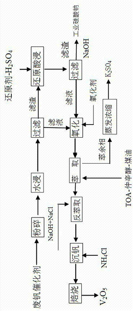
[0068] 1. Add 200 g of water to 100 g of spent vanadium catalyst with a particle size of 300 μm, and leach for 2 hours at a temperature of 90 ° C. After the water immersion, filter to obtain the water leaching filtrate and water leaching filter residue, and wash the water leaching filter residue with clear water until neutral. Separately collect water leaching residue, water leaching filtrate and lotion;

[0069] 2. In 350g mass ratio of 11% sulfuric acid solution, add 3.1 g of potassium sulfite reducing agent, and divide it into 4 parts, add the first part of leaching solution to the water leaching residue obtained in step 1, at 100 React at ℃ for 2 hours, let it stand for precipitation, and absorb the supernatant to obtain the reducing acid immersion solution. Repeat the same operation 3 more times. After reducing acid leaching, filter the reducing acid leaching filtrate and filter residue, wash the reducing acid leachi...

Embodiment 2

[0078] Present embodiment 2 carries out as follows:

[0079] 1. Add 150g of water to 100g of spent vanadium catalyst with a particle size of 355μm, leaching for 2.5 hours at a temperature of 85°C, filter the water leaching filtrate and filter residue after water leaching, wash the water leaching filter residue until neutral, and collect Water leaching residue, water leaching filtrate, lotion;

[0080] 2. In 250g of sulfuric acid solution with a mass ratio of 11%, add 2.4g of sodium sulfite reducing agent and divide it into 4 parts. Add the first leaching solution to the water leaching residue obtained in step 1, react at 90°C for 3 hours, let it stand for precipitation, and absorb the supernatant to obtain the reducing acid leaching solution. Repeat the same operation 3 more times. After reducing acid leaching, filter the reducing acid leaching filtrate and filter residue, wash the reducing acid leaching filter residue with water until neutral, collect the reducing acid leac...

Embodiment 3

[0089] Present embodiment 3 carries out as follows:

[0090] 1. Add 250g of water to 100g of spent vanadium catalyst with a particle size of 250μm, and leaching at 95°C for 1.5 hours. After the water immersion, filter to obtain the water leaching filtrate and filter residue. The water leaching filter residue is washed with water until neutral, and collected separately. Water leaching residue, water leaching filtrate, lotion;

[0091] 2. In 400g of 11% sulfuric acid solution, add 3.6 g of potassium sulfite, and divide it into 4 parts, add the first part of leaching solution to the water leaching residue obtained in step 1, and react at 95 ° C for 2.5 Hours, let it stand for precipitation, and absorb the supernatant to obtain the reducing acid immersion solution. Repeat the same operation 3 more times. After reducing acid leaching, filter the reducing acid leaching filtrate and filter residue, wash the reducing acid leaching filter residue with water until neutral, collect th...


PUM

PropertyMeasurementUnit
Granularityaaaaaaaaaa

Abstract

The invention discloses a method for recovering vanadium, potassium and silicon from a waste vanadium catalyst. The method comprises the following steps: firstly, leaching the waste vanadium catalyst in water, and leaching in a reductic acid, wherein the total leaching rate of vanadium is greater than or equal to 95.0%, separating the silicon from vanadium and potassium transferred to a leaching solution in a form of a leaching slag; preparing liquid sodium silicate to recover silicon from the leaching slag by alkali dissolution; separating the vanadium from potassium in the leaching solution in an extraction manner; preparing potassium sulphate to recover potassium from a raffinate phase in an evaporative crystallization manner; and preparing vanadium pentoxide from an extract phase by the procedures of re-extraction, molybdenum precipitation, calcination and the like. Meanwhile, the vanadium in the extract phase and the raffinate phase is larger in distribution ratio, and does not react with other metal impurities such as iron and the like due to excellent selectivity of an extraction agent TOA on vanadium, other metal impurity ions such as iron and the like do not need to be removed in advance, and the vanadium can be directly extracted. Thus, a part of edulcoration procedures are reduced, the raw material consumption is saved, and a high-purity product of vanadium can be directly prepared. By adopting the method disclosed by the invention, not only can the vanadium, potassium and silicon in the waste vanadium catalyst be comprehensively recovered, but also the targets of turning the waste into treasure and protecting the environment are achieved.

Description

technical field [0001] The invention relates to the field of catalyst recovery in the chemical industry, in particular to a recovery method for vanadium, potassium and silicon in spent vanadium catalysts. It belongs to the category of hydrometallurgy. Background technique [0002] With the development of the chemical industry, the amount of catalysts used in the production of various products is increasing, especially the amount of vanadium-containing catalysts is increasing, such as the production of sulfuric acid by contact method, desulfurization, dehydrogenation of heavy oil, synthesis of special rubber, etc. Vanadium-containing catalysts are widely used . After these catalysts have been used for a period of time, due to reasons such as poisoning, they gradually lose their catalytic effect and are scrapped, becoming vanadium-containing waste. At the same time, with the increasingly stringent environmental regulations, the disposal of these spent catalysts has become an...

Claims


Application Information

Patent Timeline
IPC IPC(8): C22B7/00C22B3/08C22B3/26C22B3/44C01B33/32C22B34/22C22B26/10
CPCY02P10/20
Inventor 郝喜才姬学亮韩艳霞石海洋王宫南曹明张镭
Owner KAIFENG UNIV
Learn More