
Building integrated air conditioner

An integrated and architectural technology, applied in buildings, building components, air-conditioning systems, etc., can solve the problems of energy loss in air-water heat exchangers, failure to provide heating in the north, and reduced efficiency, so as to save air-conditioning electricity costs, reduce operating costs, and reduce carbon emissions. low effect

Active Publication Date: 2016-01-20
沈阳领界科技有限公司
View PDF6 Cites 0 Cited by
  • Summary
  • Abstract
  • Description
  • Claims
  • Application Information

AI Technical Summary

Problems solved by technology

[0002] The current air conditioners basically use indoor side fan coils for cooling and heating. Since the specific heat of the air is very small, energy can only be transferred by convection. The temperature difference is large and the efficiency is very low. The air source hot water system is due to The minimum evaporation temperature must be below -20°C. When the condensation temperature is 50°C, no matter what refrigerant is used, the compression ratio is greater than 7, which is far beyond the working range of existing compressors and cannot be used for heating in the north.
[0003] Although the inventor has proposed a patent for low-temperature heating through capillary water pipes or geothermal water pipes, a large amount of energy will be lost in the conversion process of the air-water heat exchanger, resulting in a decrease in efficiency, and the total cost of laying water pumps, heat exchangers, and capillary water pipes is lower than that The present invention is much higher, and it is easy to freeze when the heating is stopped in winter

Method used


Image

  • Building integrated air conditioner
  • Building integrated air conditioner
  • Building integrated air conditioner

Examples


Embodiment 1

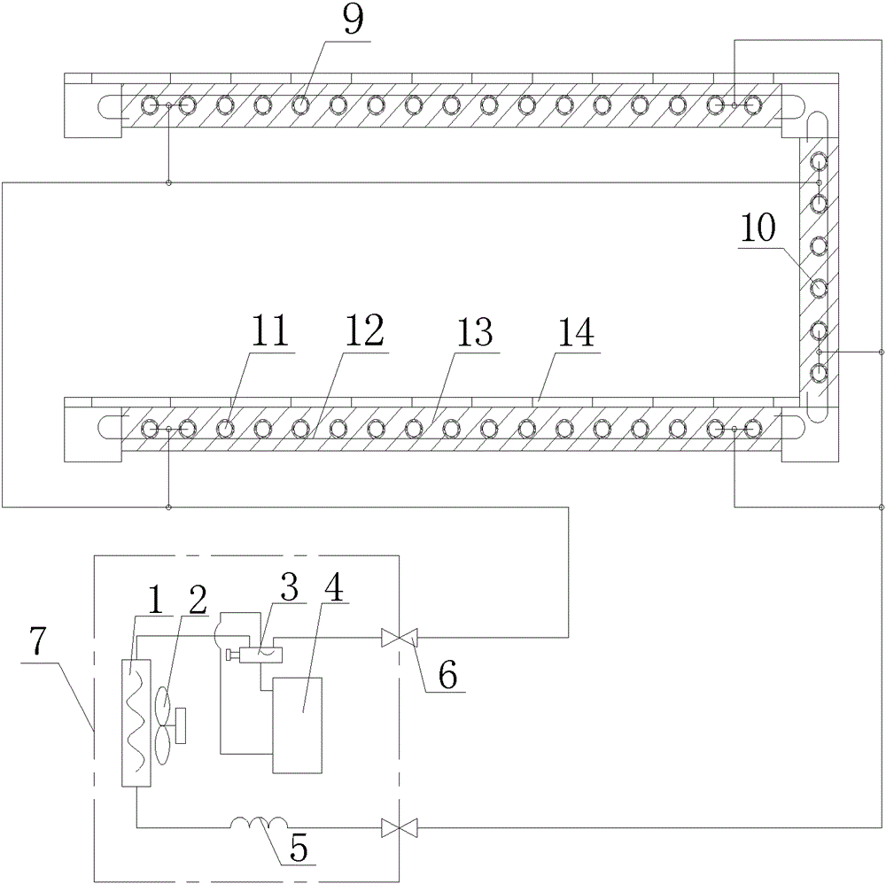
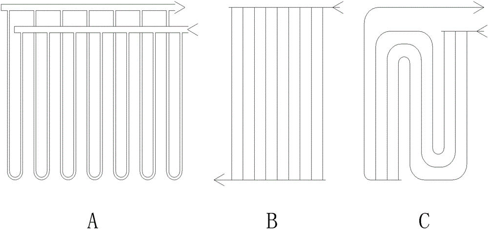
[0046] like figure 1 As shown, in a 16m wide slab building, the wall thickness is 0.6mm, the outer diameter is 2.4mm ceiling microporous pipeline 9, the pressure is 30MPa, the single length is 30m, the distance is 8cm, and the two ends are respectively welded on the guide pipe. Folded to 15m, fixed with clips in the middle to form a pipe network with a pipe distance of 4cm, such as figure 2 -A shown (can also use figure 2 -B, C plane mode), laid on site on the building steel bar 12 and tied up, and cast into one body with cement, 100m 2 A total of 2,500 extended meters are laid on the floor, and the heat exchange surface area is 18.8m 2 , the total flow cross-sectional area: 2cm 2 , Internal volume ratio: 2.8L, using 3.5-10kw carbon dioxide digital frequency conversion outdoor unit; when connecting with R410 refrigerant outdoor unit, the length of a single tube is 5-30m, and the wall thickness is 0.3-0.5mm, which can meet the pressure; The design value of the evaporation...

Embodiment 2

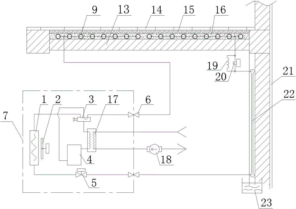
[0054] like image 3 , Figure 4 As shown, PERT or PB microporous tubes are used, the inner hole is 0.5-1 mm, the wall thickness is 1-1.5 mm, and the tube spacing is 2-3 mm. Multiple parallel welding can be pasted on the lower part of the floor 13 with cement glue, or vertically pasted on the wall Body surface, water tank 23 is set below, can also be paved on the ground with cement, sand, graphite.

[0055] Due to the low pressure of this kind of microporous tube, it is more suitable for R22, R134A, R404 and other medium and low pressure refrigerant units to work. During cold storage work in summer, segmental pressure control can be performed, the solenoid valve 20 is closed, and the throttling part 5 is adjusted. Make the cooling evaporation temperature of the pipeline 22 on the surface of the wall between 22-27°C to avoid condensation and keep the indoor temperature constant. The pressure of the return air is equal. Because the floor 13 is thicker, there will be no condens...

Embodiment 3

[0063] like Figure 5 As shown, the carbon conduit fiber cloth 26 is adopted, and the guide pipe 24 is hot-injected with plastics such as PB, PP or PE at both longitudinal ends, and bonded with high-strength heat-conducting adhesive 25 on the ground, ceiling or wall of the completed building. A reinforced adhesive layer is formed to connect the guide pipe 24 to the outdoor unit 7 .

[0064] From the pressure bearing calculation expression ρ=2·wall thickness×(tensile strength / 2) / diameter, it can be seen that the carbon fiber tube with a wall thickness of 30 μm and an inner hole of 20 μm bears a pressure greater than 10 MPa, and the surface area around the fabric tube can be greater than the laying area, while The carbon conduit also has good thermal conductivity. The thickness of the single-layer fabric paving is less than 2mm. Even if there are some accidental damage parts, the high-strength thermal conductive adhesive 25 will seal them. The cross-sectional area of ​​the flow ...


PUM


Abstract

A building-integrated air conditioner, comprising: an external heat exchanger (1), a four-way reversing valve (3), a compressor (4), and microporous pipelines (9, 10, 11). The microporous pipelines are The metal capillary is bound to the building steel bar (12) and is integrated with the concrete casting. Multiple parallel ports on one side of the microporous pipeline (9, 10, 11) are connected to the right port of the four-way reversing valve (3), and the other Multiple parallel ports on the side are connected to the lower port of the external heat exchanger (1) through the throttling component (5), and the upper port of the external heat exchanger (1) is connected to the left port of the four-way reversing valve (3), and the four-way reversing valve (3) The common port in the middle is connected to the air return port of the compressor (4), the inlet of the four-way reversing valve (3) is connected to the outlet of the compressor (4), and the external heat exchanger (1) is an air-cooled heat exchanger or a water-cooled heat exchanger , at least one of foundation pile heat exchangers, and solar panel heat exchangers. The air conditioner is reliable and durable, noiseless, maintenance-free, low carbon emissions, low heating and cooling operating costs, simple construction process, environmental protection, low cost, and can make the building itself stronger.

Description

technical field [0001] The invention relates to a building-integrated air conditioner, in particular to a building-integrated device for heating and cooling. Background technique [0002] The current air conditioners basically use indoor side fan coils for cooling and heating. Since the specific heat of the air is very small, energy can only be transferred by convection. The temperature difference is large and the efficiency is very low. The air source hot water system is due to The minimum evaporation temperature must be below -20°C. When the condensation temperature is 50°C, no matter what refrigerant is used, the compression ratio is greater than 7, which is far beyond the working range of existing compressors and cannot be used for heating in the north. [0003] Although the inventor has proposed a patent for low-temperature heating through capillary water pipes or geothermal water pipes, a large amount of energy will be lost in the conversion process of the air-water he...

Claims


Application Information

Patent Timeline
Patent Type & Authority Patents(China)
IPC IPC(8): F24D3/10F24F12/00E04F17/08
CPCF24F5/0085F24D3/14F24D3/18F24D2200/11F24D2200/12F24D2200/123F24D2220/006Y02B10/40F24F5/0089F24F5/0092F28F1/40F28F1/22F28D2021/0035F28F2260/02Y02B30/12Y02B30/00F25B13/00
Inventor 奉政一
Owner 沈阳领界科技有限公司
Learn More