
Supercapacitor battery

A technology for supercapacitors and batteries, which is applied in the directions of hybrid capacitor electrodes, hybrid capacitor terminals, hybrid capacitor separators, etc., and can solve problems such as limitations in the field of supercapacitor batteries.

Active Publication Date: 2014-08-13
扬州荣可然科技有限公司
View PDF6 Cites 5 Cited by
  • Summary
  • Abstract
  • Description
  • Claims
  • Application Information

AI Technical Summary

Problems solved by technology

[0009] In Chinese patent 201120513423.5, a power supercapacitor is introduced, which includes a metal case, a positive electrode fixed on the metal case and insulated from it, a negative electrode fixed on the metal case and electrically connected to it, encapsulated in the metal case At least one core unit in the core unit, the core unit is composed of an anode sheet, a cathode sheet, and a diaphragm arranged between the anode sheet and the cathode sheet; adjacent core units are separated by a diaphragm, and adjacent The core units are electrically connected by lead wires; wherein, the anode piece of the uppermost core unit is electrically connected to the positive pole, and the cathode piece of the lowermost core unit is electrically connected to the negative pole to form a power supercapacitor. The materials used in the invention are also common raw materials, which limits the application field of the supercapacitor battery of the invention

Method used

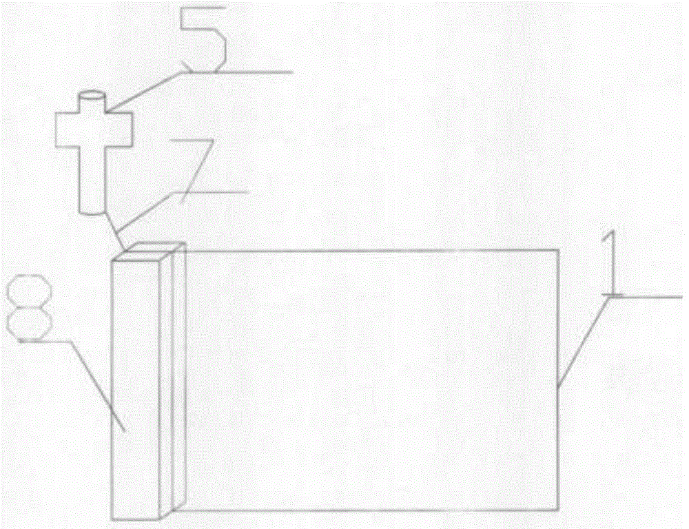
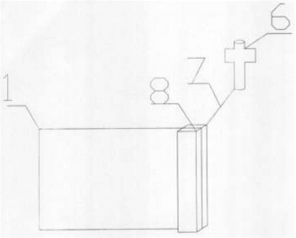
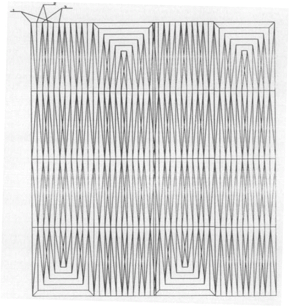

Image

  • Supercapacitor battery
  • Supercapacitor battery
  • Supercapacitor battery

Examples


Embodiment 1

[0032] Organosilicon powder is carbonized at high temperature into silicon carbide powder. The mass ratio of silicon carbide powder to polyphenylene sulfide resin is 84:16. At the same time, metal titanium or α-titanium alloy is embedded in the electrode mold. The phenylene sulfide resin is hot-pressed at a temperature of 260°C and a pressure of 1.2Mpa to form a supercapacitor battery electrode. The electrode is pre-embedded with multiple strands of metal titanium or titanium alloy strands, and is connected by titanium or titanium alloy strands at a thickness of The 8um metal titanium or titanium alloy thin end plate is in contact with the ultra-high viscosity NMP electrolyte of lithium methylaminobutyrate, lithium polysulfide, lithium perchlorate, and lithium phosphate, and then the 18um polyphenylene sulfide film is used as the The diaphragm becomes half of the supercapacitor battery; then the polyphenylene sulfide film is in contact with the diaphragm and is an ultra-high vi...

Embodiment 2

[0034] Organosilicon powder is carbonized at high temperature into silicon carbide powder. The mass ratio of silicon carbide powder to polyphenylene sulfide resin is 84:16. At the same time, metal titanium or α-titanium alloy is embedded in the electrode mold. The phenylene sulfide resin is hot-pressed at a temperature of 280°C and a pressure of 1.0Mpa to form a supercapacitor battery electrode. The electrode is pre-embedded with multiple strands of metal titanium or titanium alloy strands, and is connected by titanium or titanium alloy strands at a thickness The 18um metal titanium or titanium alloy thin end plate is in contact with the ultra-high viscosity NMP electrolyte of lithium methylaminobutyrate, lithium polysulfide, lithium perchlorate, and lithium phosphate, and then the 33um polyphenylene sulfide film is used as the The diaphragm becomes half of the supercapacitor battery; then the polyphenylene sulfide film is in contact with the diaphragm and is an ultra-high visc...

Embodiment 3

[0036] Organosilicon powder is carbonized at high temperature into silicon carbide powder. The mass ratio of silicon carbide powder to polyphenylene sulfide resin is 84:16. At the same time, metal titanium or α-titanium alloy is embedded in the electrode mold. The phenylene sulfide resin is hot-pressed at a temperature of 268°C and a pressure of 1.1Mpa to form a supercapacitor battery electrode. The electrode is pre-embedded with multiple strands of metal titanium or titanium alloy strands, and is connected by titanium or titanium alloy strands at a thickness of The 16um metal titanium or titanium alloy thin end plate is in contact with the ultra-high viscosity NMP electrolyte of lithium methylaminobutyrate, lithium polysulfide, lithium perchlorate, and lithium phosphate, and then the 28um polyphenylene sulfide film is used as the The diaphragm becomes half of the supercapacitor battery; then the polyphenylene sulfide film is in contact with the diaphragm and is an ultra-high v...


PUM

PropertyMeasurementUnit
Diameteraaaaaaaaaa
Diameteraaaaaaaaaa
Thicknessaaaaaaaaaa

Abstract

The invention discloses a supercapacitor battery. The supercapacitor battery is mainly composed of electrodes, an electrolyte, a membrane, end plates, a lead and a packaging material. The main conductive material of the electrodes is silicon carbide. The electrode lead is directly connected with the battery end plates in a welding mode through a multi-strand sterepsinema with the diameter ranging from 1 mm to 4 mm, and the multi-strand sterepsinema is made of metallic titanium fibers or titanium alloy fibers. The NMP ultrahigh viscosity solution of methylamino butyric acid lithium, polysulfide lithium, lithium perchlorate and lithium phosphate serves as the electrolyte. A polyphenylene sulfide thin film serves as the membrane. The end plates are made of metallic titanium or titanium alloy. The packaging material is formed by welding an ultra-thick polyphenylene sulfide injection molding part and a thin film in a laser mode. One electrode, one end plate, the electrolyte, the membrane, the electrolyte, the other end plate and the other electrode are overlapped in sequence or wound into the 88-188 layers of the supercapacitor battery. The supercapacitor battery has the advantages of being high in temperature resistance, low in temperature resistance, corrosion resistant, short in charging time, large in number of circulation times and long in service life, and can be widely applied to places with the very hostile environmental conditions.

Description

technical field [0001] The invention relates to battery manufacturing, especially the technical field of power batteries. Background technique [0002] With the continuous development of the economy, it will inevitably lead to the depletion of oil resources, environmental pollution, and the aggravation of global warming. The development and comprehensive and efficient utilization of new energy, energy-saving technology and environmental technology has become a very necessary subject, and the development of electric vehicles is imperative. Supercapacitors have obvious advantages in the field of electric vehicles, which can meet the high power requirements of vehicles during acceleration, starting, and climbing to protect the main battery system. [0003] If used in conjunction with the power battery, the supercapacitor can act as a large current or energy buffer, reduce the damage to the power battery caused by high current charging and discharging, prolong the service life ...

Claims


Application Information

Patent Timeline
IPC IPC(8): H01G11/78H01G11/52H01G11/74H01G11/32H01G11/84
Inventor 宋大余徐晨李波
Owner 扬州荣可然科技有限公司
Learn More