A photoelectric nuclear battery
A nuclear battery and optoelectronic technology, applied in the fields of nuclear energy applications, micro-energy, and nuclear physics, can solve the problems of low output power, low energy conversion efficiency, and high sunlight dependence of fluorescent nuclear batteries, and achieve flexible battery design and good chemistry. Stability, the effect of expanding the application field
- Summary
- Abstract
- Description
- Claims
- Application Information
AI Technical Summary
Problems solved by technology
Method used
Image
Examples
Embodiment 1
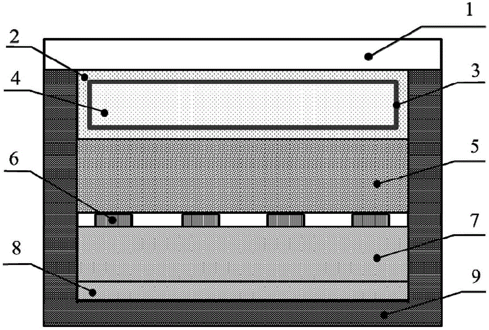
[0038] Step 1. Select a quartz glass sheet with a light transmittance of 95% and a resistance to 1000°C as the substrate of the fluorescent layer, wash it repeatedly with deionized water and alcohol, and dry it for later use;
[0039] Step 2. Deposit a layer of ZnS:Cu fluorescent layer 5 with a thickness of 70 μm on the substrate by physical deposition technology, place the deposited sample at 250° C. for 30 minutes, and wait for it to cool naturally to room temperature. It can be taken out to complete the preparation of the radioluminescent layer, and the whole preparation environment is normal pressure;
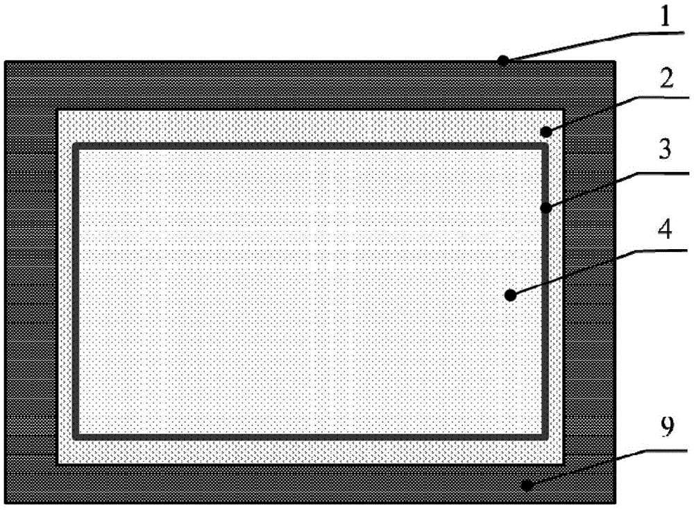
[0040]Step 3: Prepare the peripheral structure of the nuclear battery. The substrate of the sealed casing 9 is DPC, that is, a direct copper-plated support in which copper is deposited on the Al2O3 support by direct coating technology. This kind of ceramic material has a high thermal conductivity, which can improve the heat dissipation efficiency of the battery, and the thi...
Embodiment 2
[0045] This example is the same as Example 1 except for the following points.
[0046] Step 1. Select a colorless and transparent epoxy resin with a viscosity of 4500-5500MPa·s at room temperature and a colorless and transparent curing agent with a viscosity of 350-500MPa·s, and pre-treat the phosphor powder, preheating at 50-60°C for a period of time time;
[0047] Step 2. Mix the epoxy resin and curing agent in a weight ratio of 2:1 by using adhesive compounding technology, and mix it with Y 2 o 2 S: Stir the Eu phosphor evenly, heat and solidify, remove the corners and trim it to a suitable size, and complete the preparation of the phosphor layer;
[0048] Step five, load the Y on top of the semiconductor layer 2 o 2 S: A fluorescent layer made of Eu phosphor powder and transparent glue, on which a layer of glass capsule containing a gaseous tritium source is continuously loaded to form the radiation-induced fluorescent nuclear battery part;
Embodiment 3
[0050] This example is the same as Example 1 except for the following points.
[0051] Step 5. Load the ZnS:Cu fluorescent layer and the gaseous tritium source wrapped by elastic transparent glass on the top of the photovoltaic module to form the radiofluorescent nuclear battery part, and add a supercapacitor and voltage-stabilizing output device to it to convert the low-power , Discontinuous and dispersed electric energy collection and storage;
[0052] Step 6. Coating the transparent window above the entire peripheral structure with a double layer of TiO with better chemical stability 2 / Al 2 o 3 Anti-reflection film dielectric system material, and then package the various units of the battery together to complete the preparation of a micro-photoelectric nuclear battery integrating photoluminescence and radiofluorescence. Wherein, the area of the active region of the radioactive isotope and the light-absorbing surface area of the semiconductor layer are slightly small...
PUM
 Abstract
Description
Claims
Application Information
 - R&D
- Intellectual Property
- Life Sciences
- Materials
- Tech Scout
- Unparalleled Data Quality
- Higher Quality Content
- 60% Fewer Hallucinations
Browse by: Latest US Patents, China's latest patents, Technical Efficacy Thesaurus, Application Domain, Technology Topic, Popular Technical Reports.
© 2025 PatSnap. All rights reserved.Legal|Privacy policy|Modern Slavery Act Transparency Statement|Sitemap|About US| Contact US: help@patsnap.com


