
Non-contact micro arc polishing process and device thereof

A non-contact, micro-arc technology, applied in the field of material processing, can solve problems affecting mechanical properties such as fatigue strength of components

Inactive Publication Date: 2014-10-29
NANJING UNIV OF TECH
View PDF5 Cites 3 Cited by
  • Summary
  • Abstract
  • Description
  • Claims
  • Application Information

AI Technical Summary

Problems solved by technology

Non-contact polishing includes electric spark, ultraviolet laser, particle beam and other methods. These technologies can meet the processing accuracy requirements, but in principle they all belong to thermal processing technology, which will produce refraction larger than one micron or even ten microns on the processed surface. The casting layer, microcracks and residual stress, etc., which in turn affect the mechanical properties of the component such as fatigue strength

Method used


Image

  • Non-contact micro arc polishing process and device thereof
  • Non-contact micro arc polishing process and device thereof
  • Non-contact micro arc polishing process and device thereof

Examples


Embodiment approach 1

[0026] In this embodiment, an aluminum alloy sample is used, and the steps of micro-arc polishing are as follows:

[0027] Step (1): configuration electrolyte, the present embodiment uses (NaPO 3 ) 6 As the main electrolyte, NaOH solution is used as an additive at the same time. The volume of the solution is 80L, the total concentration of the solution is 40g / L, and the NaOH is 1.2g / L. Stir evenly and adjust the pH value to 7-10.

[0028] Step (2): Design the cathode and anode parameters, use stainless steel as the cathode material, the cross-sectional shape is circular, and the diameter is 30×30mm, and the cathode is aligned with the aluminum alloy so that the distance between the electrodes is 30mm.

[0029] Step (3): Control the flow field environment. According to the requirements of polishing and removal, this embodiment adopts a top-down fluid pipeline, and the flow field velocity is controlled at 0.8m / s.

[0030] Step (4): Set the power supply parameters, select the c...

Embodiment approach 2

[0035] In this embodiment, a magnesium alloy sample is used, and the steps of micro-arc polishing are as follows:

[0036] Step (1): Configure the electrolyte. In this embodiment, silicate is used as the main electrolyte, and NaHCO 3 The solution is an additive, the added concentration is 3g / L, the solution volume is 80L, the total concentration of the solution is 40g / L, and the mixture is evenly stirred.

[0037] Step (2): Adjust the distance between the cathode and the anode. The cathode is a square stainless steel plate with a size of 150mm×250mm, so that the cathode is aligned with the anode magnesium alloy, and the pole spacing is 80mm.

[0038] Step (3): Control the flow field environment. According to the requirements of polishing and removal, this embodiment adopts a top-down fluid pipeline, and the flow field velocity is 1m / s.

[0039] Step (4): Set the power supply parameters, select the constant voltage mode for the power supply mode, the pulse frequency is 20KHz, ...


PUM

PropertyMeasurementUnit
Roughnessaaaaaaaaaa

Abstract

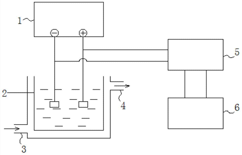
The invention relates to the field of material processing and in particular relates to a metal product surface non-contact micro arc polishing process and device thereof. The process comprises the following steps: preparing electrolyte, designing parameters of the cathode and anode, controlling a flow field environment, setting parameters of a power supply and performing micro arc polishing. The device comprises a micro arc polishing power supply and an electrolytic cell, wherein the electrolyte is arranged in the electrolytic cell; two poles of the micro arc polishing power supply are inserted into the electrolyte; a cooling water system is arranged at the periphery of the electrolytic cell; and the two poles of the micro arc polishing power supply are electrically connected with a control system through a signal acquisition unit. With adoption of the process and device, the micro arc polishing process has the advantage that atomic-scale layer-by-layer stripping can be performed, the process defect of inconsistent interference of the electrode potential is overcome, the process is not limited by anode metal components and phase composition, complex curved surface shape members can be met, and the process aims of sub-micron to nano-scale precision polishing and machining requirements can be achieved.

Description

technical field [0001] The invention relates to the field of material processing, in particular to a non-contact micro-arc polishing process and a device for the surface of metal products. Background technique [0002] Magnesium, aluminum, titanium and other metals and their alloys have advantages such as small specific gravity, good thermal conductivity, high specific strength and specific stiffness, easy processing and rich resources, etc., making them widely used in aerospace, automobile industry, communication electronics industry, light industry and building materials. , petrochemical, biomedicine and other fields have been increasingly widely used, showing a very wide range of application prospects. However, such alloy products mostly adopt one-time molding processes such as die-casting and extrusion, and the complex overall shape makes it difficult to implement mechanical contact grinding and polishing precision shaping methods. It is particularly important to develop...

Claims


Application Information

Patent Timeline
IPC IPC(8): C25D11/02
Inventor 蒋百铃阚金峰李洪涛张超刘燕婕
Owner NANJING UNIV OF TECH
Learn More