Substrate based bumped flip chip CSP (Chip Scale Package) package part, substrate and manufacturing method

A flip-chip, manufacturing method technology, applied in semiconductor/solid-state device manufacturing, electrical components, electrical solid-state devices, etc., can solve problems such as large differences and mismatched thermal expansion coefficients, and achieve small capacitance, thin shape, and good heat dissipation performance. Effect

Inactive Publication Date: 2014-12-10
TIANSHUI HUATIAN TECH
View PDF5 Cites 6 Cited by
  • Summary
  • Abstract
  • Description
  • Claims
  • Application Information

AI Technical Summary

Problems solved by technology

However, after the silicon chip (silicon die) is installed on the ceramic substrate, the thermal expansion coefficient (CTE) of the ceramic substrate and the PCB substrate do not match and the difference is too large (the CTE of the ceramic substrate is 6-8ppm / ℃, and the CTE of the PCB substrate is 16~19ppm / ℃), it is difficult to place the ceramic substrate on the PCB substrate

Method used


Image

  • Substrate based bumped flip chip CSP (Chip Scale Package) package part, substrate and manufacturing method
  • Substrate based bumped flip chip CSP (Chip Scale Package) package part, substrate and manufacturing method
  • Substrate based bumped flip chip CSP (Chip Scale Package) package part, substrate and manufacturing method

Examples


Embodiment 1

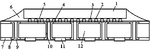
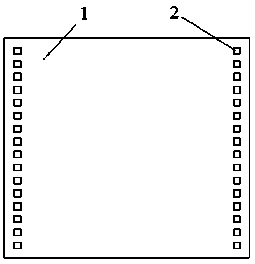
[0085] Design the substrate according to the requirements of use; the raw material of the substrate is FR-4 copper-clad laminate, and the raw material of the substrate includes the middle layer of the substrate covered with a copper layer on the upper surface and the lower surface; according to the design requirements of the substrate, mechanical drilling is used to drill holes on the substrate A plurality of holes through the raw material of the substrate are formed on the raw material; a cylindrical side wall of copper with uniform thickness is electroplated on the surface of the hole, and the two ends of the side wall are respectively connected with the copper on the upper surface and the lower surface of the middle layer of the substrate. The layers are connected; a layer of dry film is respectively laid on the copper layer on the upper and lower surfaces of the original substrate, and the dry film on the two layers of copper except for the graphic part is removed by exposur...

Embodiment 2

[0087] The substrate is obtained by the method of Example 1, and the passivation layer, the passivation layer opening, the sputtering Ti layer and the Cu layer are coated on the substrate according to the method of Example 1, and the photoresist is coated to form a thickness of 35.5 mm. μm photoresist layer, baked at 85°C for 18 seconds to make the photoresist and Ti / Cu layer tightly bonded; .

Embodiment 3

[0089] The substrate is obtained according to the method of Example 1, and the passivation layer, the opening of the passivation layer, the sputtering Ti layer and the Cu layer are coated on the substrate according to the method of Example 1, and the photoresist is coated to form a thickness of 34.5 μm photoresist layer, baked at 75°C for 12 seconds to make the photoresist and Ti / Cu layer tightly bonded; .


PUM


Abstract

The invention discloses a substrate based bumped flip chip CSP (Chip Scale Package) package part, a substrate and a manufacturing method. The package part comprises the substrate and an IC (Integrated Circuit) chip which is inversely installed on the substrate; padding is filled between the substrate and the IC chip; the substrate comprises a substrate middle layer with an upper surface and a lower surface provided with printing lines; the substrate middle layer is provided with a plurality of cylindrical lateral walls which are connected with the printing lines; the upper face and the lower face of the substrate middle layer are provided with substrate bonding pads which are connected with the printing lines. The substrate is manufactured by procedures such as drilling, electrofacing, paving a dry film, exposing and developing with an FR-4 copper-clad plate or a BT substrate serving as substrate raw materials. The CSP package part is obtained by passivating a wafer; forming a UBM layer on the chip bonding pad; coating photoresist; duplicating patterns on a photoresist layer; forming into a stannum / plumbum metal layer; obtaining welding bumped points through backflow; inversely install the chip; melting the welding bumped points; downward filling and obtaining a CSP package part. The package part solves the problems that lead bonding package high-frequency electrical performance is poor and thermal expansion between the ceramic substrate and the PCB is large in mismatch during the existing IC package circuit connection.

Description

technical field [0001] The invention belongs to the technical field of semiconductor packaging for electronic device manufacturing, and relates to a bump flip-chip CSP package based on a substrate; the invention also relates to a substrate used in the package, and the invention further relates to a package of the package Manufacturing method. Background technique [0002] With the increasing development of electronic information technology, integrated circuit packaging is developing towards high performance on the one hand, and developing towards thinner and smaller on the other hand. In IC packaging, the connection between the chip and the substrate (lead frame) provides a circuit connection for the distribution of power and signals. There are three ways to realize the internal connection of the IC chip package: wire bonding, automatic welding and flip chip weld. At present, more than 90% of the IC chip connection methods are still wire bonding. Due to the long bonding wi...

Claims


Application Information

Patent Timeline
Patent Type & Authority Applications(China)
IPC IPC(8): H01L23/31H01L21/50
CPCH01L2224/11H01L2224/16225H01L2224/32225H01L2224/73204H01L2924/00
Inventor 邵荣昌慕蔚李习周张易勒周建国张胡军张进兵
Owner TIANSHUI HUATIAN TECH
Why Eureka
Try Eureka