Butt-joint low-resistance lead for electronic packaging and manufacturing method thereof

An electronic packaging, low-resistance lead technology, applied in welding equipment, auxiliary welding equipment, welding/cutting auxiliary equipment, etc., can solve the problems that the resistance is not suitable for the passage of large current, the space is limited, the lead is increased, and the structure is simple, The effect of convenient processing and low cost

Inactive Publication Date: 2015-03-25
NO 43 INST OF CHINA ELECTRONICS TECH GRP CETC
View PDF4 Cites 4 Cited by
  • Summary
  • Abstract
  • Description
  • Claims
  • Application Information

AI Technical Summary

Problems solved by technology

[0003] In order to make the thermal expansion coefficient of the lead wire close to that of glass to meet the reliability requirements of glass-metal sealing, low-expansion alloy materials such as iron-nickel alloys (such as Kovar alloy, 4J50 alloy, etc.) or iron-nickel alloy copper-clad lead materials are usually used (such as Kovar copper-clad composite lead material, 4J50 alloy copper-clad composite lead material, etc.), but its resistance is still not suitable for large currents to pass through
In addition, the higher...

Method used


Image

  • Butt-joint low-resistance lead for electronic packaging and manufacturing method thereof
  • Butt-joint low-resistance lead for electronic packaging and manufacturing method thereof
  • Butt-joint low-resistance lead for electronic packaging and manufacturing method thereof

Examples


Embodiment 1

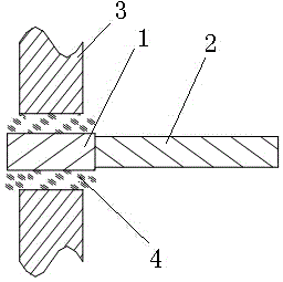
[0038] like figure 1 As shown, the butt-joint low-resistance lead for electronic packaging is formed by butting the ends of the feed-through lead segment 1 and the low-resistance lead segment 2 through resistance welding or brazing coaxial welding. The material of the low-resistance lead segment 2 A metal material having a resistivity lower than that of the feedthrough lead segment 1 is selected, and the resistivity of the metal material is ≤2 μΩ·cm. The length of the feedthrough lead segment 1 matches the length of the encapsulating glass 4 , and the diameter is larger than that of the low-resistance lead segment 1 .

[0039] Preferably, the low-resistance lead segment 2 is made of oxygen-free copper, zirconium bronze or diffused oxygen-free copper. Feedthrough lead section 1 is a low-expansion metal lead material with a linear expansion coefficient of 4-10ppm / ℃, including iron-nickel alloys (such as Kovar alloy, 4J50 alloy, etc.) and iron-nickel alloy-clad copper lead mater...

Embodiment 2

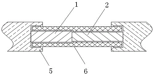
[0042] like figure 2 As shown, the resistance welding method of butt-type low-resistance leads for electronic packaging, the steps are as follows:

[0043] (1) Use a grinder to grind the butt end faces of the feedthrough lead segment 1 and the low resistance lead segment 2, so that the flatness of the end face is 0.01 mm and the surface roughness is 0.8 μm, and then the end faces of the two lead segments to be welded are stacked perpendicular to the horizontal plane Neat, restrained by a metal ring, the front and back sides are ground into a smooth plane, and the burrs are removed;

[0044](2) Put the feedthrough lead segment 1 and the low-resistance lead segment 2 through the positioning insulating sleeve 6, and the length of which extends out of the positioning insulating sleeve 6 is 1 mm, so as to ensure that the two lead segments will not be bent and deformed after the end face is stressed; Clamp the positioning insulating sleeve 6 on both sides of the welding electrode ...

Embodiment 3

[0047] use as figure 2 The resistance welding method shown, the steps are as follows:

[0048] (1) Use a grinder to grind the butt end faces of the feedthrough lead segment 1 and the low resistance lead segment 2, so that the flatness of the end face is 0.008 mm and the surface roughness is 0.87 μm, and then the end faces of the two lead segments to be welded are vertical to the horizontal plane and stacked neatly. Constrained by a metal ring, the front and back sides are ground into smooth planes respectively, and the burrs are removed;

[0049] (2) Put the feedthrough lead segment 1 and the low-resistance lead segment 2 through the positioning insulating sleeve 6, and extend the length of the positioning insulating sleeve 6 by 0.5mm to ensure that the two lead segments will not be bent and deformed after the end face is stressed; Clamp the positioning insulating sleeve 6 on both sides of the welding electrode 5, adjust the power of the resistance welding machine to reach t...


PUM

PropertyMeasurementUnit
Resistivityaaaaaaaaaa
Linear expansion coefficientaaaaaaaaaa
Lengthaaaaaaaaaa

Abstract

The invention provides a butt-joint low-resistance lead for electronic packaging and a manufacturing method of the butt-joint low-resistance lead for electronic packaging. The butt-joint low-resistance lead comprises a feed-through lead segment, wherein one end of the feed-through lead segment is in butt joint with a low-resistance lead segment, and the length of the feed-through lead segment is matched with the length of packaged glass; the low-resistance lead segment is made of metal materials with the electric resistivity smaller than that of the materials of the feed-through lead segment, and the electric resistivity of the metal materials is smaller than or equal to 2 microhm*cm. According to the butt-joint low-resistance lead for electronic packaging, the feed-through lead segment and the low-resistant lead segment are welded into a whole through electric resistance welding and a brazing method. The manufactured butt-joint low-resistance lead for electronic packaging is high in butt-joint strength, small in resistance and suitable for making high current pass; the butt-joint low-resistance lead for electronic packaging is resistant to high temperature and not prone to annealing deformation at the high temperature of 950 DEG C. Thus, the requirements of a power electronic device shell for high lead current carrying of the lead and high lead arrangement density are both met.

Description

technical field [0001] The invention relates to the field of electronic packaging, in particular to a butt joint low-resistance lead for electronic packaging and a preparation method thereof. Background technique [0002] With the continuous pursuit of integration and power density of the hybrid integrated circuit power casing, the casing of the power electronic device is a lead wire of a metal casing, which needs to take into account the characteristics of large current carrying and high wiring density. amount of power consumption. In addition, due to the requirements of heat dissipation and air tightness, metal leads are usually packaged through glass insulators in lead packaging, forming a metal-glass-metal lead structure. Therefore, the thermal expansion coefficients of metal leads and glass are required to be similar, reaching or close to matching sealing. catch. [0003] In order to make the thermal expansion coefficient of the lead wire close to that of glass to m...

Claims


Application Information

Patent Timeline
IPC IPC(8): B23K37/00
CPCH01L24/43H01L24/45H01L2224/432H01L2224/43H01L2224/451
Inventor 阚云辉张志成
Owner NO 43 INST OF CHINA ELECTRONICS TECH GRP CETC
Why Eureka
Try Eureka