
Photoelectrochemical kinetics test system and method based on scanning electrochemical microscope

A scanning electrochemistry and photoelectrochemistry technology, applied in measurement devices, scientific instruments, instruments, etc., can solve the problems of cumbersome experimental operation and data analysis, imperfect information capture technology, and unclear mechanism, and achieve simple data processing steps. Clear, conducive to promotion and application, easy to control effects

Inactive Publication Date: 2015-04-08
HUAZHONG UNIV OF SCI & TECH
View PDF6 Cites 11 Cited by
  • Summary
  • Abstract
  • Description
  • Claims
  • Application Information

AI Technical Summary

Problems solved by technology

[0004] At present, there are many forms of solar energy utilization, mainly in the three working forms of photovoltaic cells, photocatalysis and photoelectric catalysis. The application technology in these aspects has made great progress, but the scientific community does not understand some mechanisms of these three working forms. It is clear that, in particular, information capture techniques for photoelectrochemical interfacial reaction kinetics are imperfect
Although the current transient absorption spectrometer can also test the interface dynamic behavior of some optoelectronic devices, but because the instrument needs to be imported from abroad for a long time, the price is expensive, the requirements for the use environment are high, and the experimental operation and data analysis are cumbersome. Photoelectrochemical interfacial dynamics test system and method with low cost, simple operation and easy data analysis

Method used


Image

  • Photoelectrochemical kinetics test system and method based on scanning electrochemical microscope
  • Photoelectrochemical kinetics test system and method based on scanning electrochemical microscope
  • Photoelectrochemical kinetics test system and method based on scanning electrochemical microscope

Examples


Embodiment 1

[0042] In this embodiment, the photoelectrochemical kinetics testing method based on scanning electrochemical microscope comprises the following steps:

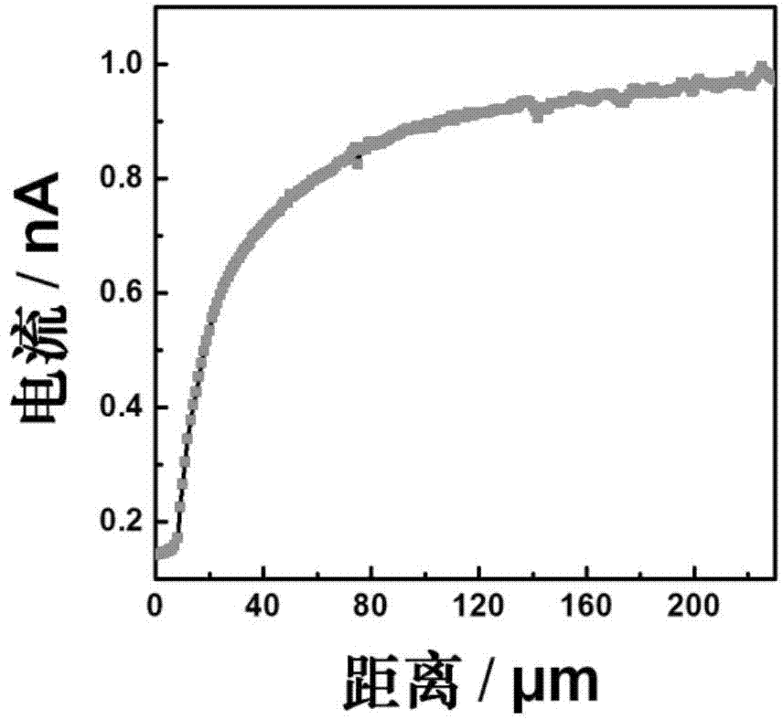
[0043] S1. Preparation of redox electrolyte. In this embodiment, the cobalt electrolyte Co(bpy) 3 (PF 6 ) 3 As an example, take acetonitrile CH 3 CN is the solvent, tetrabutylammonium perchlorate C 16 h 36 ClNO 4 For the supporting electrolyte, prepare cobalt electrolyte Co(bpy) with a series of concentrations of 1mM, 0.8mM, 0.6mM, 0.3mM, 0.1mM and 0.03mM respectively 3 (PF 6 ) 3 For the redox electrolyte, take 2mL electrolyte with a certain concentration each time and add it to the PTFE reaction cell;

[0044] S2. Prepare the base electrode. P25 TiO 2 The paste was prepared by screen printing onto the conductive glass FTO to form TiO 2 thin film, then annealed in an annealing furnace at 500°C for 30 minutes and then cooled naturally. When the temperature dropped to 80°C, the FTO / TiO 2 The film was soaked into th...

Embodiment 2

[0054] In this embodiment, the photoelectrochemical kinetics testing method based on scanning electrochemical microscope comprises the following steps:

[0055] S1. Preparation of redox electrolyte. In this example, the polysulfide electrolyte T 2 As an example, take acetonitrile CH 3 CN is the solvent, tetrabutylammonium perchlorate C 16 h 36 ClNO 4 For the supporting electrolyte, prepare 1mM, 0.6mM, 0.3mM, 0.1mM, a series of concentrations of polysulfide electrolyte T 2 For the redox electrolyte, take 2mL electrolyte of a specific concentration and fill it into the PTFE reaction cell each time;

[0056] S2. Preparation of the base electrode. P25 TiO 2 The paste was prepared by screen printing onto conductive glass FTO to form TiO with a diameter of 7mm 2 The film was then annealed in an annealing furnace at 500°C for 30 minutes and cooled naturally. Obtaining FTO / TiO by Ion Adsorption 2 / CdSe thin film, at this time the photoanode thin film preparation of quantum d...

Embodiment 3

[0066] In this embodiment, the photoelectrochemical kinetics testing method based on scanning electrochemical microscope comprises the following steps:

[0067] S1. Preparation of redox electrolyte. In this embodiment, potassium ferricyanide K 3 Fe(CN) 6 For example, with deionized water as solvent, sodium sulfate Na 2 SO 4 For supporting electrolyte, prepare potassium ferricyanide K with a series concentration of 4.0mM, 2.0mM, 0.6mM, 0.3mM, 0.1mM 3 Fe(CN) 6 For the redox electrolyte, take 2mL of the electrolyte with the above concentration and add it to the PTFE reaction cell;

[0068] S2. Preparation of the base electrode. The conductive glass FTO was used as the base electrode, and bismuth nitrate Bi(NO 3 ) 3 , potassium iodide KI and p-benzoquinone C 6 h 4 o 2 The aqueous solution is used as the electrolyte, and the potential of the substrate electrode is set to -0.1V by electrochemical constant potential deposition method, and the FTO / BiOI electrode is obtained...


PUM

PropertyMeasurementUnit
Diameteraaaaaaaaaa

Abstract

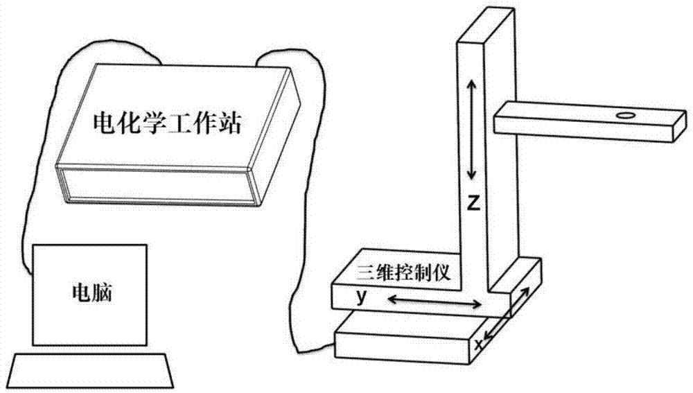
The invention discloses a photoelectrochemical kinetics test system and method based on a scanning electrochemical microscope. The system includes a scanning electrochemical microscope device, a Pt ultra microelectrode, a sample fixing device, a light source device and a rotary table control device. The scanning electrochemical microscope comprises a three-dimensional control device and an electrochemical workstation. The sample fixing device comprises a PTFE chemical tank and a fixed part. The light source device comprises a radiator, a DC power supply and red, yellow, blue and white LED light sources arranged on the edge of the radiator disc in order. The rotary table control device comprises a central processor, a disc with light through hole, a controller and a stepper motor. The invention can overcome the defect of insufficient information acquisition in the current solar cell and photoelectrocatalysis interfacial chemical reaction kinetics, quickly get accurate information of interfacial reaction kinetics, and provide strong experimental parameters for researching solar cells or photoelectrocatalysis water decomposition device.

Description

technical field [0001] The present invention relates to the technical field of photoelectrochemical interface dynamics, in particular to a photoelectrochemical kinetic testing system and method based on a scanning electrochemical microscope. Background technique [0002] With the depletion of global fossil energy, it is becoming more and more urgent to find alternative renewable energy for human beings. With the continuous development of new energy technologies, as representatives of renewable energy, the utilization of nuclear energy, wind energy and solar energy has begun to slowly enter people's daily life. The development and utilization of solar energy has become the research focus of governments and scientific circles. [0003] Scanning Electrochemical Microscopy (SECM) is a scanning probe microscopy technique proposed and developed by the internationally renowned electrochemist A.J. Bard's group in the late 1980s. It is based on the development of ultramicroelectrode...

Claims


Application Information

Patent Timeline
IPC IPC(8): G01N23/227
Inventor 申燕张炳雁张晓凡王鸣魁袁怀亮
Owner HUAZHONG UNIV OF SCI & TECH
Learn More