Implementation of avalanche photo diodes in (BI) CMOS processes

A photodiode and process technology, applied in the field of medical imaging, can solve the problems of large volume, obstructed design rules, poor working effect, etc., and achieve the effect of increasing detection efficiency

Inactive Publication Date: 2015-04-22
KONINK PHILIPS ELECTRONICS NV
View PDF2 Cites 5 Cited by
  • Summary
  • Abstract
  • Description
  • Claims
  • Application Information

AI Technical Summary

Problems solved by technology

Photomultipliers have several disadvantages as vacuum devices: they are bulky, require high voltages, and do not work well in strong magnetic fields
Furthermore, although all required processing steps are usually available in standard CMOS or BiCMOS processes, their application to form the required guard ring structures is often hampered by design rules, and many such diode designs have to use Tricks to implement a guard ring with a given unchanged CMOS or BiCMOS process

Method used


Image

  • Implementation of avalanche photo diodes in (BI) CMOS processes
  • Implementation of avalanche photo diodes in (BI) CMOS processes
  • Implementation of avalanche photo diodes in (BI) CMOS processes

Examples


Embodiment Construction

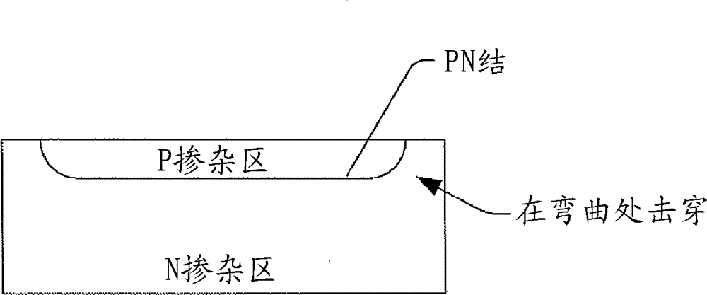
[0023] refer to figure 2 and 3 , which show photodiodes 10 fabricated to suppress, reduce, eliminate, etc., the premature edge breakdown associated with conventional photodiodes driven in conventional Geiger or other modes, such as avalanche photodiodes (APDs) . figure 2 depicts a side view of photodiode 10, image 3 A top view of photodiode 10 is depicted.

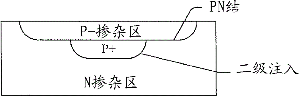
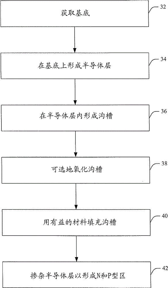
[0024] The photodiode 10 includes a semiconductor layer 12 (eg, silicon (Si), germanium (Ge), gallium arsenide (GaAs), etc.) formed (eg, by photolithography, lithography, etc.) in on a substrate 14 (eg, silicon, glass, sapphire, etc. wafer). The semiconductor layer 12 includes an n-type (n− doped) well 16 arranged adjacent to a p-type (p+ doped) region 18 , between which a pn junction is formed. Such regions are formed by known techniques such as ion implantation (in which ions are implanted, thereby altering the physical properties of semiconductor layer 12 ), diffusion, and / or the like.

[0025] A trench 20 is f...


PUM


Abstract

A radiation detector (46) includes a semiconductor layer(s) (12) formed on a substrate (14) and a scintillator (30) formed on the semiconductor layer(s) (12). The semiconductor layer(s) (12) includes an n-doped region (16) disposed adjacent to the substrate (14), and a p-doped region (18) disposed adjacent to the n-doped region (16). A trench (20) is formed within the semiconductor layer(s) (12) and around the p-doped region (18) and is filled with a material (22) that reduces pn junction curvature at the edges of the pn junction, which reduces breakdown at the edges. The scintillator (30) is disposed over and optically coupled to the p-doped regions (18). The radiation detector (46) further includes at least one conductive electrode (24) that electrically contacts the n-doped region.

Description

technical field [0001] The present invention relates to medical imaging technology. It finds particular application to photodiodes such as avalanche photodiodes used in medical imaging systems and / or other applications. Background technique [0002] In positron emission tomography (PET), two simultaneously generated 511 keV gamma photons are detected with the aid of a scintillation crystal. Scintillation crystals detect gamma photons and convert some of their energy into light quanta with energies in the blue part of the electromagnetic spectrum. These photons are then detected by one or more photodetectors, typically photomultipliers. The number of detected photons indicates the actual energy of the gammas, which may be below 511 keV due to dispersion in the patient's body. The timing of the gamma strike is defined by the rising edge of the photodetector signal. Generally, for coincidence logic, temporal resolution in the nanosecond range is sufficient to detect simulta...

Claims


Application Information

Patent Timeline
Patent Type & Authority Applications(China)
IPC IPC(8): H01L29/861H01L21/329
CPCH01L31/1804H01L27/1446H01L31/115H01L31/107Y02E10/547Y02P70/50
Inventor A. 赫林加T. 弗拉克P. 阿加沃尔
Owner KONINK PHILIPS ELECTRONICS NV
Why Eureka
Try Eureka