
Preparation method of Mn-based rodlike microtopography composite oxide low-temperature denitrification catalyst

A composite oxide and microscopic morphology technology, applied in metal/metal oxide/metal hydroxide catalysts, physical/chemical process catalysts, chemical instruments and methods, etc., can solve the problem of accelerating the deposition of ammonium sulfate species on the surface of catalysts, catalysts Shortened service life, poisonous vanadium-containing catalyst, etc., to achieve good low-temperature denitrification performance, wide range of low-temperature denitrification performance, and simple preparation methods

Active Publication Date: 2015-05-20
DALIAN UNIV OF TECH
View PDF4 Cites 10 Cited by
  • Summary
  • Abstract
  • Description
  • Claims
  • Application Information

AI Technical Summary

Problems solved by technology

[0003] At present, it is generally believed that selective catalytic reduction (SCR) denitrification technology is one of the most effective means to control NO pollutants in flue gas. The V-W-Ti system and its modified catalyst are relatively mature in industrial application, but the catalyst still exists. Some shortcomings are mainly manifested in: (1) the vanadium-containing catalyst is poisonous and easily pollutes the environment; (2) the applicable temperature of the vanadium-containing catalyst is relatively high, generally 350°C and above; (3) during the use of the vanadium-containing catalyst, prone to SO 2 to SO 3 conversion, accelerate the deposition of ammonium sulfate species on the surface of the catalyst, and shorten the service life of the catalyst

Method used


Image

  • Preparation method of Mn-based rodlike microtopography composite oxide low-temperature denitrification catalyst
  • Preparation method of Mn-based rodlike microtopography composite oxide low-temperature denitrification catalyst
  • Preparation method of Mn-based rodlike microtopography composite oxide low-temperature denitrification catalyst

Examples


Embodiment 1

[0023] 1) Weigh 9.80g Mn(CH 3 COO) 2 4H 2 O, 17.45g Ni(NO 3 ) 2 ·6H 2 O, 1.20g Cu(CH 3 COO) 2 2H 2 O, 5.48g Ce(NH 4 ) 2 (NO 3 ) 6 and 24.01g CO(NH 2 ) 2 Dissolve in 40ml, 40ml, 10ml, 10ml and 200ml of distilled water respectively, and keep stirring at room temperature until the solution is completely clear. The salt solution and CO(NH 2 ) 2 The solution was mixed well, and distilled water was added to increase the total volume of the mixed solution to 500 ml.

[0024] 2) The mixed solution was placed in an oil bath at 60° C., and the reaction was continued for 5 hours under stirring conditions, and a yellow-green precipitate was obtained after the reaction was completed.

[0025] 3) The obtained sample was washed with water, washed with alcohol, separated, and dried at 70° C. for 12 hours to obtain a Mn-based composite oxide catalyst precursor.

[0026] 4) Put the fully dried sample into a muffle furnace to program the temperature from room temperature to 550°...

Embodiment 2

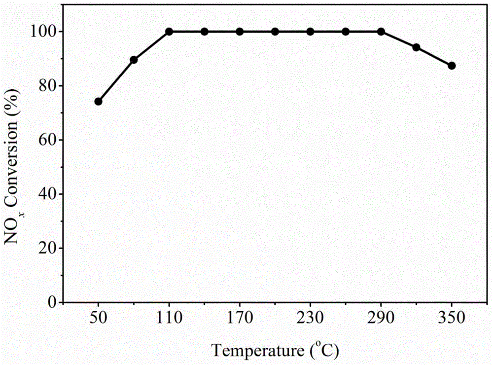
[0028] Put 0.2g of granular Mn-based rod-shaped composite oxide catalyst with a particle size of 40-60 mesh in the flue gas simulation reaction device, and test the NO removal effect of the catalyst under different temperature conditions. The simulated flue gas composition is 500ppm NO , 500ppm NH 3 , 10vol.%O 2 , He is the balance gas, and the air velocity of the simulated flue gas is 30,000h -1 . NO of Mn-based composite oxide catalysts with rod-like micro-morphology x The change curve of conversion rate with temperature is as follows: figure 1 shown.

[0029] The reaction results show that the Mn-based rod-like microscopic composite oxide catalyst has high low-temperature activity. As the reaction temperature increases, the NO of the catalyst x The conversion rate gradually increased. The catalyst has a wide temperature operating window, and its NO x The conversion rate can reach more than 90%, and it can maintain 100% NO in the temperature range of 110-290°C x Conv...

Embodiment 3

[0030] Example 3: Flue gas space velocity sensitivity test of Mn-based rod-shaped microscopic composite oxide catalyst

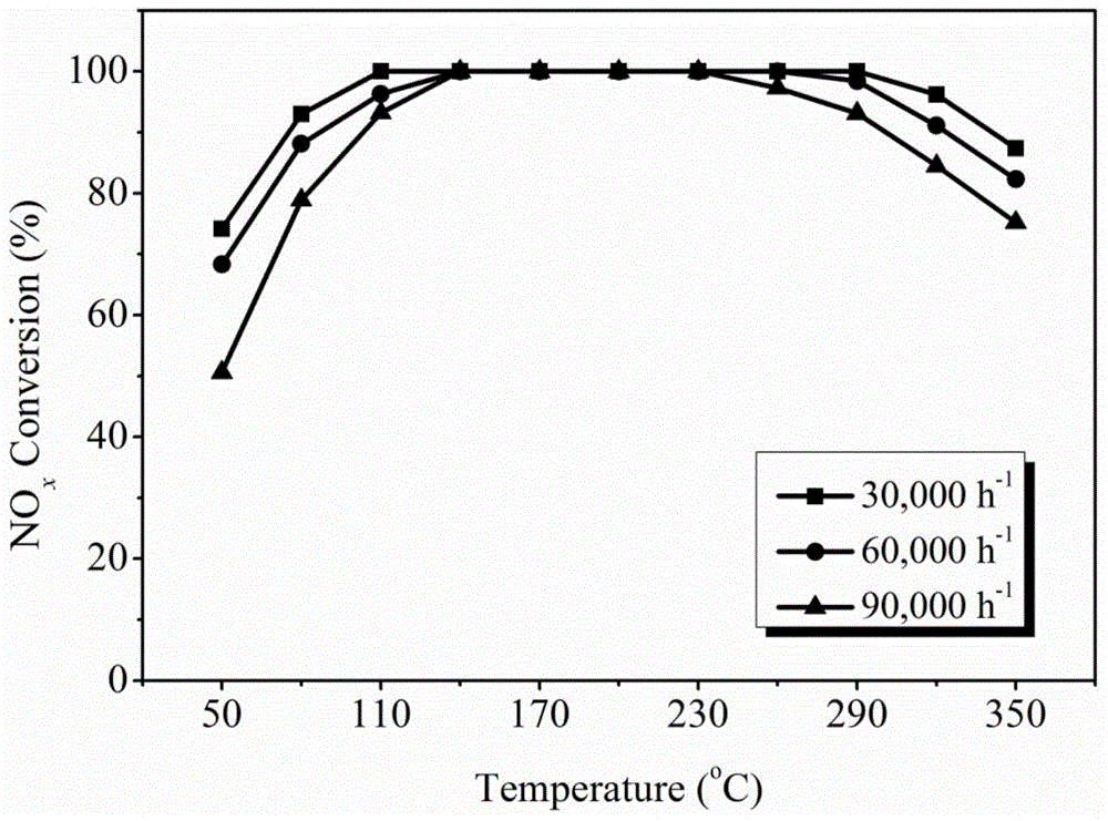
[0031] Put 0.2g granular Mn-based rod-shaped composite oxide catalyst with a particle size of 40-60 mesh in the flue gas simulation reaction device, test the effect of simulated flue gas space velocity changes on the denitrification effect of the catalyst, and simulate flue gas composition 500ppm NO, 500ppm NH 3 , 10vol.%O 2 , He is the balance gas, and the air velocity of the simulated flue gas during the test is 30,000h -1 、60,000h -1 and 90,000h -1 . The test results of denitrification performance of Mn-based rod-shaped microscopic composite oxide catalysts under different flue gas space velocities are as follows: image 3 shown.

[0032] The reaction results show that the Mn-based rod-like microscopic composite oxide is not sensitive to the change of reaction space velocity, and has a high prospect of industrial application.


PUM

PropertyMeasurementUnit
particle size (mesh)aaaaaaaaaa

Abstract

The invention discloses a preparation method of a Mn-based rodlike microtopography composite oxide low-temperature denitrification catalyst, and belongs to the field of pollution control and techniques. The preparation method comprises the following steps of dissolving salt precursors of metal elements into distilled water to prepare a salt solution by taking MnOx as a catalyst and one or more of Ag, Cu, Fe, Ce and Co as additives, wherein NiOx is the important active component of the catalyst; and meanwhile, preparing a urea aqueous solution, mixing the salt solution and the urea aqueous solution uniformly, stirring and crystallizing at the reaction temperature of 50-120 DEG C for 4-12 hours, filtering, washing, drying, and forging and the like to prepare the Mn-based rodlike microtopography composite oxide low-temperature denitrification catalyst. The catalyst is applied to the selective catalytic reduction (NH3-SCR)NO by adopting NH3 as a reducing agent. The Mn-based rodlike microtopography composite oxide low-temperature denitrification catalyst has good low-temperature denitrification performance, is simple and convenient to prepare, is mild in condition, and has good application value in the denitrification field based on the NH3-SCR technique.

Description

technical field [0001] The invention belongs to the field of gas purification and denitration catalyst preparation, and relates to a preparation method of a flue gas denitration catalyst, in particular to a preparation method of a Mn-based rod-shaped microscopic composite oxide low-temperature denitration catalyst. Background technique [0002] Nitrogen oxides (NO x ) is an important cause of environmental problems such as acid rain, photochemical smog, ozone depletion, and haze weather, and is an air pollutant that needs to be controlled. NO x It can cause human emphysema, vision loss, bronchitis and other diseases, seriously endangering human health, and can also cause great harm to crops and buildings. NO produced by various pollution sources x Predominantly in the form of NO, while NO in other forms x Relatively small. [0003] At present, it is generally believed that selective catalytic reduction (SCR) denitrification technology is one of the most effective means ...

Claims


Application Information

Patent Timeline
Patent Type & Authority Applications(China)
IPC IPC(8): B01J23/889B01D53/86B01D53/56
Inventor 李新勇刘洁王晓梅肇启东李宏志孙文博
Owner DALIAN UNIV OF TECH
Learn More